Cutting tool with enhanced chip evacuation capability and method of making same

a cutting tool and enhanced technology, applied in the field of multi-flute cutting tools, can solve the problems of reducing the volume of the flute, not adding much strength, and certain flute shapes that cannot be mathematically achieved, and achieve the effect of effective chip evacuation and effective chip evacuation

Active Publication Date: 2018-01-30
KENNAMETAL INC
View PDF58 Cites 15 Cited by
  • Summary
  • Abstract
  • Description
  • Claims
  • Application Information

AI Technical Summary

Benefits of technology

[0010]In one aspect of the invention, a solid mill cutter comprises a shank; a cutting head attached to the shank, the cutting head having a plurality of helical teeth, each tooth including a cutting tip, a leading face and a rear face; and a flute defined between the leading face of a trailing tooth, and a rear face of an immediately preceding tooth, wherein a gully of the flute has a flute base with a portion that is generally planar or convex in profile to provide additional volume for effective chip evacuation.
[0016]whereby the grinding wheel forms the helical flute with a gully having a flute base with a portion that is planar or convex in profile to provide additional volume for effective chip evacuation.

Problems solved by technology

The aforementioned input imposes strict bounds for the calculations, resulting in certain flute shapes to be mathematically impossible to achieve.
The disadvantage of the common flute shape can be seen in the resultant shape of the rear face 110 of the flute 105, where a bulge of substrate material is left, thereby reducing the volume of the flute 105 without adding much strength.
This disadvantage becomes much more distinct when implementing multi-flute milling cutters with six (6) or more flutes.
Shortage of available space impose an insolvable task for common flutes to provide enough volume for chip evacuation, while providing sufficient tooth width.
As a result, many conventional multi-flute cutters have problems with the adequate evacuation of chips.

Method used


Image

  • Cutting tool with enhanced chip evacuation capability and method of making same
  • Cutting tool with enhanced chip evacuation capability and method of making same
  • Cutting tool with enhanced chip evacuation capability and method of making same

Examples


Embodiment Construction

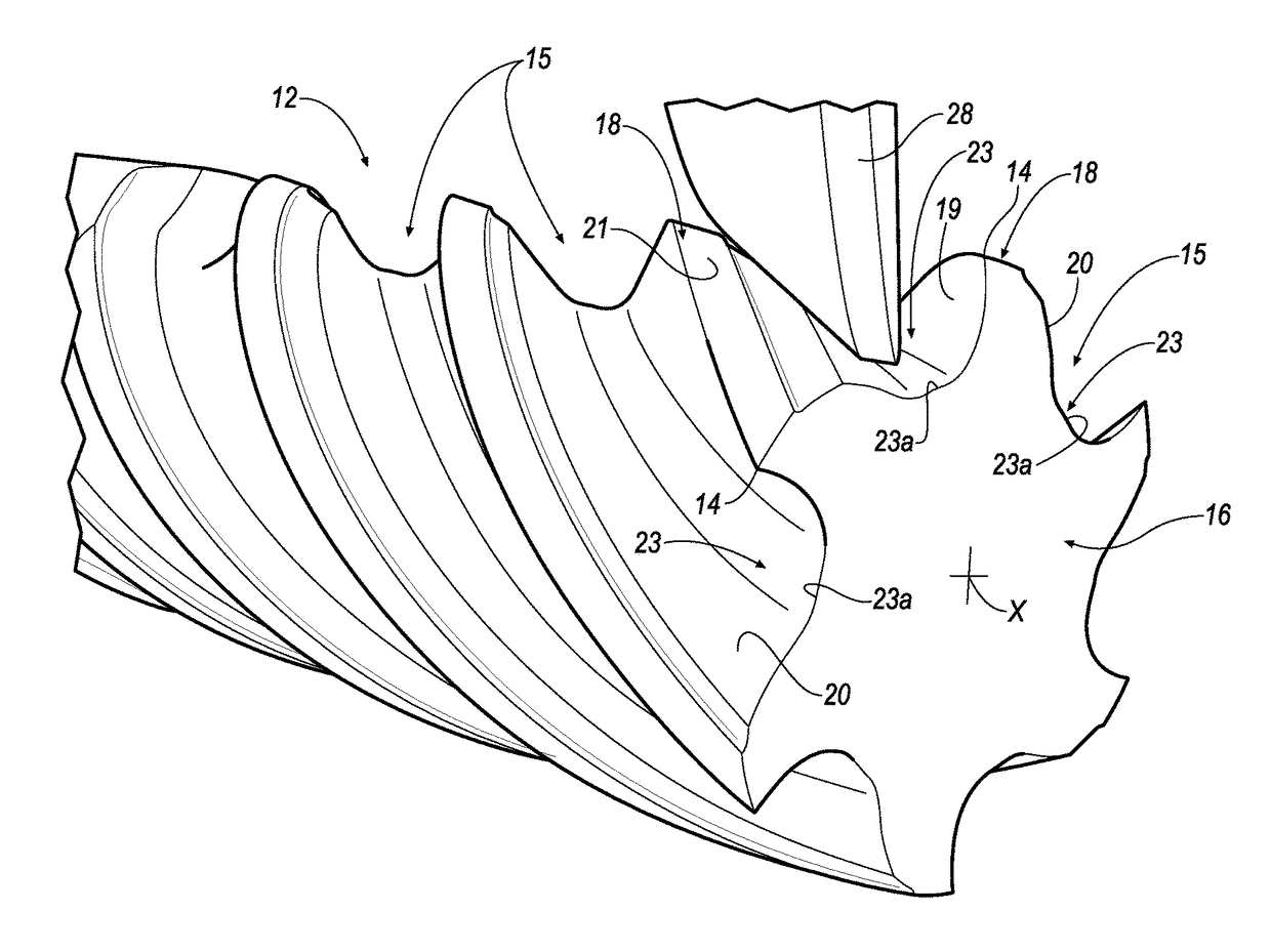
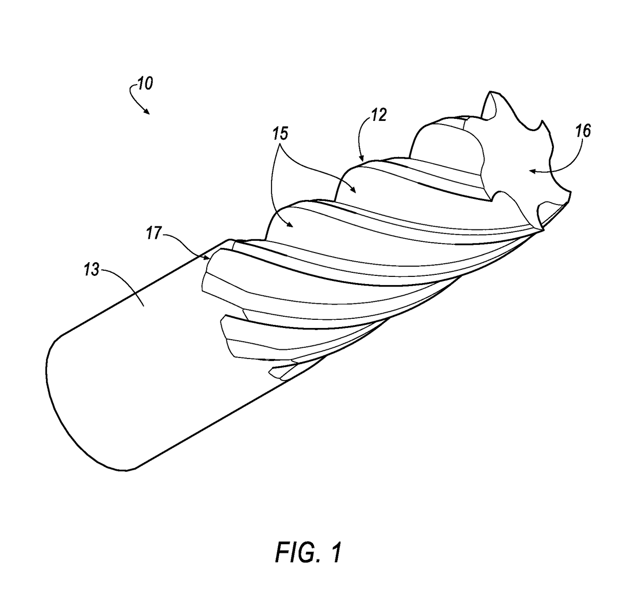
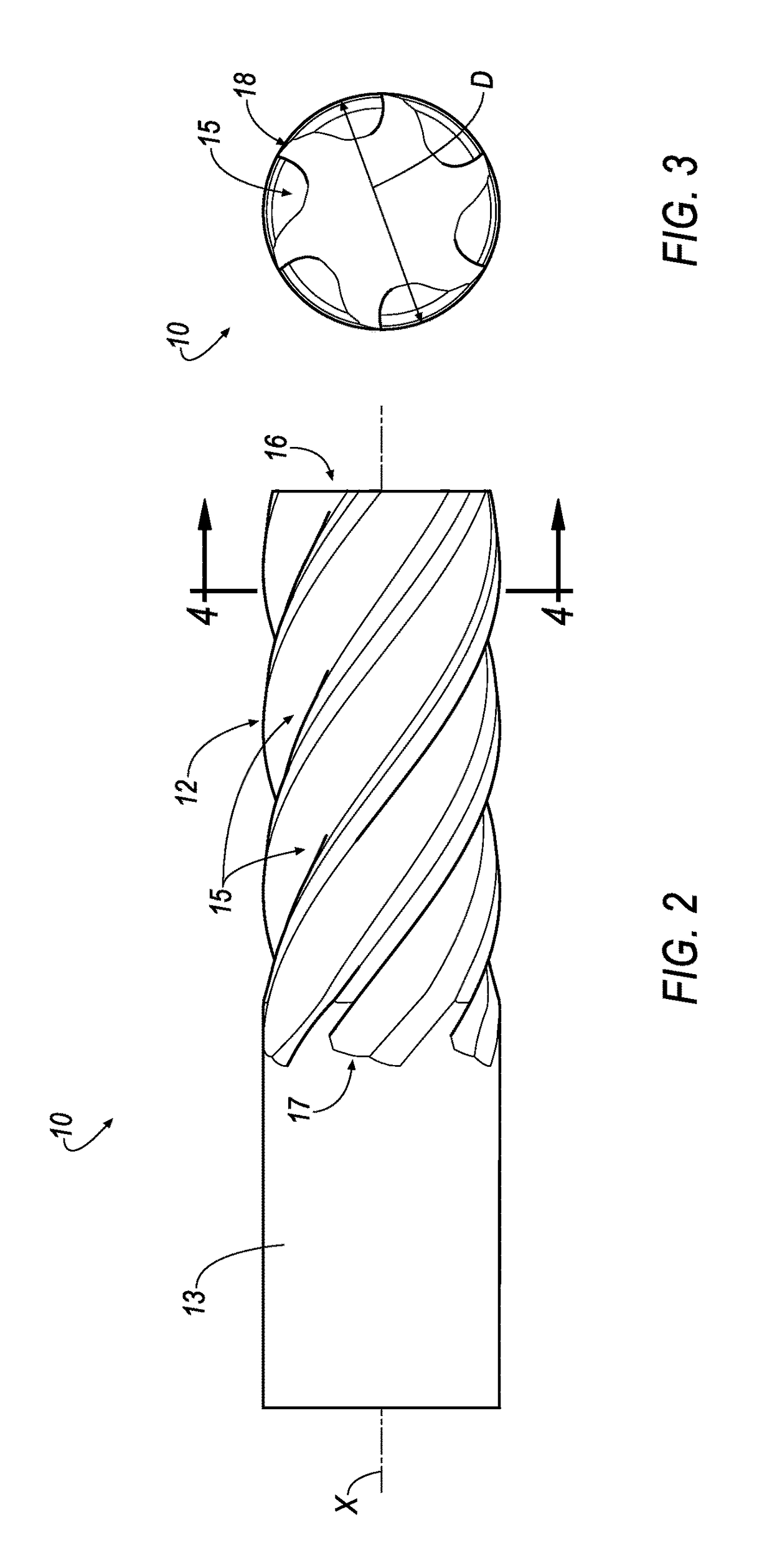
[0030]A cutting tool 10, for example, a milling cutter, is shown in FIGS. 1-6 according to an embodiment of the invention. Although a milling cutter 10 is shown in the illustrated embodiment, the principles of the invention described below can be applied to other rotary cutting tools, such as solid drills, taps, reamers, and the like. The milling cutter 10 has a cutting head 12 and a coaxial integral shank 13 for securing in a chuck or arbor of a machine tool for rotation about an axis, X.

[0031]The cutting head 12 has a plurality of helical flutes 15 extending from a leading end 16 of the head 12, to a trailing end 17 of the head 12. In the illustrated embodiment, the cutting head 12 has a total of six (6) flutes 15. However, it will be appreciated that the invention can be practiced with any desirable number of flutes 15, depending on the dimensions of the milling cutter 10. For example, a milling cutter 10 having a relatively large cutting diameter D has the capability of having a...


PUM

PropertyMeasurementUnit
clearance angleaaaaaaaaaa
wedge angleaaaaaaaaaa
cutting diameteraaaaaaaaaa

Abstract

A milling cutter includes a shank and a cutting head attached to the shank. The cutting head has a plurality of helical teeth, each tooth including a cutting tip, a leading face and a rear face. A flute is defined between the leading face of a trailing tooth, and a rear face of an immediately preceding tooth. A gully of the flute has a flute base with a portion that is planar or convex in profile to provide additional volume for effective chip evacuation. A method for manufacturing the milling cutter includes rotating a cylindrical blank about its own longitudinal axis, rotating a disc-shaped flute grinding wheel) about a rotational axis of a flute wheel and moving the grinding wheel in a longitudinal direction so as to form the helical flute with the gully having the flute base with the planar or convex portion in profile.

Description

BACKGROUND OF THE INVENTIONField of the Invention[0001]The invention pertains to the field of cutting tools. More particularly, the invention pertains to a multi-flute cutting tool having a flute that is W-shaped in cross section for superior chip evacuation (i.e., removal of swarf).Description of Related Art[0002]A conventional milling cutter 100 is illustrated in FIGS. 10-12. The cutter 100 has a cutting head 102 and a coaxial integral shank 103 for securing in a chuck or arbor of a machine tool for rotation about an axis X.[0003]The cutting head 102 has a plurality of helical flutes 105 extending from a leading end 106 of the head 102, to a trailing end 107 of the head 102. Each flute 105 has a tooth 108 provided with a leading face 109 and a rear face 110, as shown in FIG. 12. The leading face 109 faces the direction of rotation of the cutter 100 when in use and has a cutting tip 104.[0004]As shown in FIG. 10, each tooth 108 also has a primary relief rake facet 112 which, in the...

Claims


Application Information

Patent Timeline
Patent Type & Authority Patents(United States)
IPC IPC(8): B23C5/10B24B3/06B24B3/02
CPCB23C5/10B24B3/021B24B3/06B23C2210/40B23C2210/0457B23C2210/0478B23C2210/241B23C2210/0435B23C5/1081B23C2210/04B24B19/022
Inventor DAVIS, DANNY RAY
Owner KENNAMETAL INC
Why Eureka
Try Eureka