Quick release device

a technology of releasing device and crank, which is applied in the direction of vehicle crank, mechanical apparatus, vehicle components, etc., can solve the problems of reducing the strength of the crank, high manufacturing cost, and complicated manufacturing process, and achieve the effect of easy assembly/disassembly of the crank and pedal

Inactive Publication Date: 2010-09-16
CHEN CHUNG I
View PDF5 Cites 5 Cited by
  • Summary
  • Abstract
  • Description
  • Claims
  • Application Information

AI Technical Summary

Benefits of technology

[0007]The main objective of the present invention is to provide an improved quick release device which permits user to assemble / disassemble the crank and pedal easily.

Problems solved by technology

The manufacturing processes are complicated and precise; therefore the manufacturing costs are high.
The enlarged mounting hole in the crank also reduces the strength of the crank.

Method used


Image

  • Quick release device
  • Quick release device
  • Quick release device

Examples


Embodiment Construction

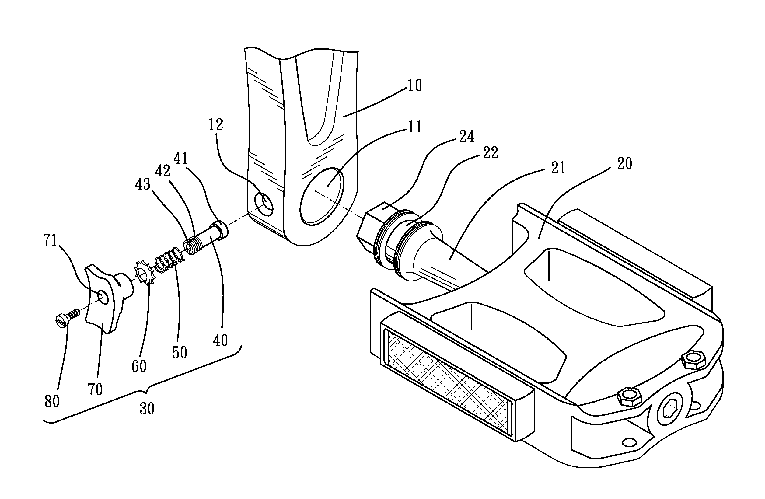
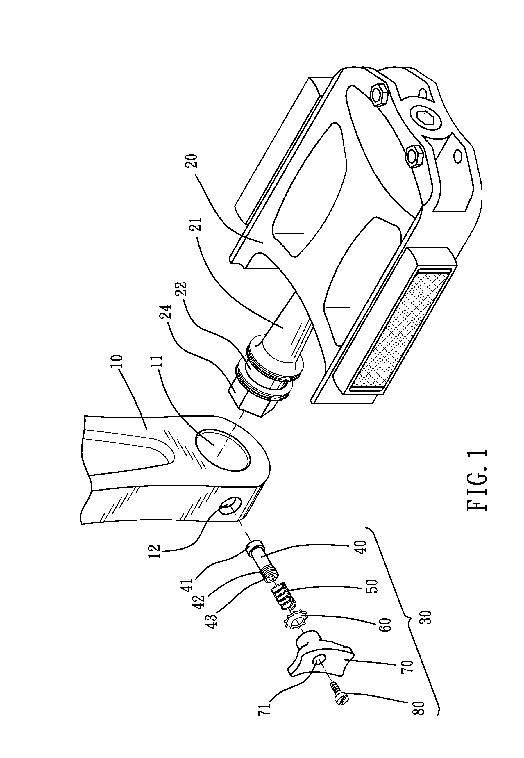
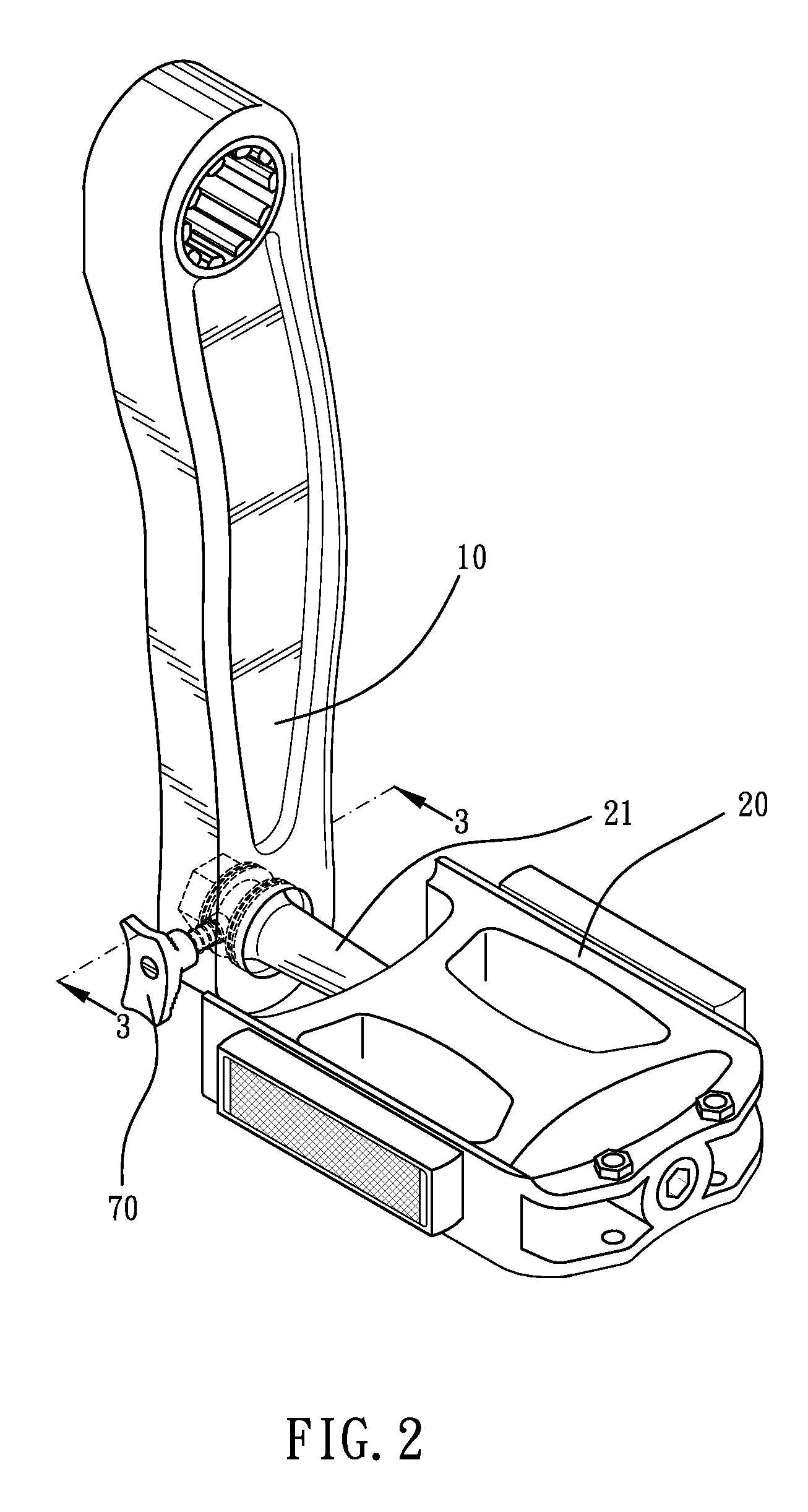
[0016]Referring to the drawings and initially to FIGS. 1-4, a quick release device in accordance with the present invention comprises a crank 10 and a pedal 20 connected to the crank 10.

[0017]The crank 10 has a pedal hole 11 defined in one end thereof. The cranks 10 has a quick release hole 12 defined in a lateral thereof. The quick release hole 12 is communicated with the pedal hole 11 and perpendicular to the pedal hole 11. The crank 10 has an engaging hole 13 (see FIG. 4) defined therein and communicated with the pedal hole 11. The engaging hole 13 is in a shape of hexagon.

[0018]The pedal 20 includes a pedal spindle 21. The pedal spindle 21 is inserted into the pedal hole 11. The pedal spindle 21 has an annular groove 22 defined therein and corresponding to the quick release hole 12. The pedal spindle 21 has an engaging protrusion 24 formed in one end thereof and corresponding to the engaging hole 13. The engaging protrusion 24 is in a shape of hexagon. In other embodiment, the e...


PUM


Abstract

A quick release device includes a crank and a quick release assembly. The crank has a pedal hole and a quick release hole. The quick release hole is communicated with the pedal hole. The quick release assembly is partially received in the quick release hole. The quick release assembly includes a rod received in the quick release hole, a spring sleeved on the rod, a stopper mounted in the quick release hole, and a pull button connected to the rod. The rod has an enlarged head formed in one end thereof. One end of the spring is abutted against the enlarged head and the other end of the spring is abutted against the stopper such that the enlarged head protrudes into the pedal hole. When pulling the pull button, the enlarged head retracts into the quick release hole.

Description

BACKGROUND OF THE INVENTION[0001]1. Field of the Invention[0002]The present invention relates to a quick release device, and more particularly to a quick release device for a bicycle crank and a bicycle pedal.[0003]2. Description of Related Art[0004]A conventional quick release device in accordance with the prior art comprises a pedal, a fixing threaded sleeve and a crank arm. The pedal has one end formed with a rotation shaft which has a free end formed with a screw portion having an outer thread. The fixing threaded sleeve has a center formed with a screw bore screwed on the screw portion of the rotation shaft of the pedal. The fixing threaded sleeve has an outer wall protruded with two radially opposite locking flanges. The crank arm has a free end formed with a mounting hole for insertion of the fixing threaded sleeve. The mounting hole of the crank arm has a wall formed with two insertion guide grooves for insertion of the two locking flanges of the fixing threaded sleeve. Each...

Claims


Application Information

Patent Timeline
Patent Type & Authority Applications(United States)
IPC IPC(8): B62M3/08
CPCY10T74/2168B62M3/08
Inventor CHEN, CHUNG-I
Owner CHEN CHUNG I
Why Eureka
Try Eureka