Inferential flow meter for use in fuel dispensing environments

a flow meter and fuel dispensing technology, applied in the field of flow meters, can solve problems such as substantial flow pulsations and errors in viscosity calculation and flow ra

Active Publication Date: 2010-09-16
GILBARCO ITAL SRL
View PDF12 Cites 21 Cited by
  • Summary
  • Abstract
  • Description
  • Claims
  • Application Information

AI Technical Summary

Problems solved by technology

Various events—such as the operation of submersible turbine pump (STP) motors, the operation of valves in the fuel flow p...

Method used


Image

  • Inferential flow meter for use in fuel dispensing environments
  • Inferential flow meter for use in fuel dispensing environments
  • Inferential flow meter for use in fuel dispensing environments

Examples


Embodiment Construction

[0024]It is to be understood by one of ordinary skill in the art that the present discussion is a description of exemplary embodiments only, and is not intended as limiting the broader aspects of the present invention, which broader aspects are embodied in the exemplary constructions.

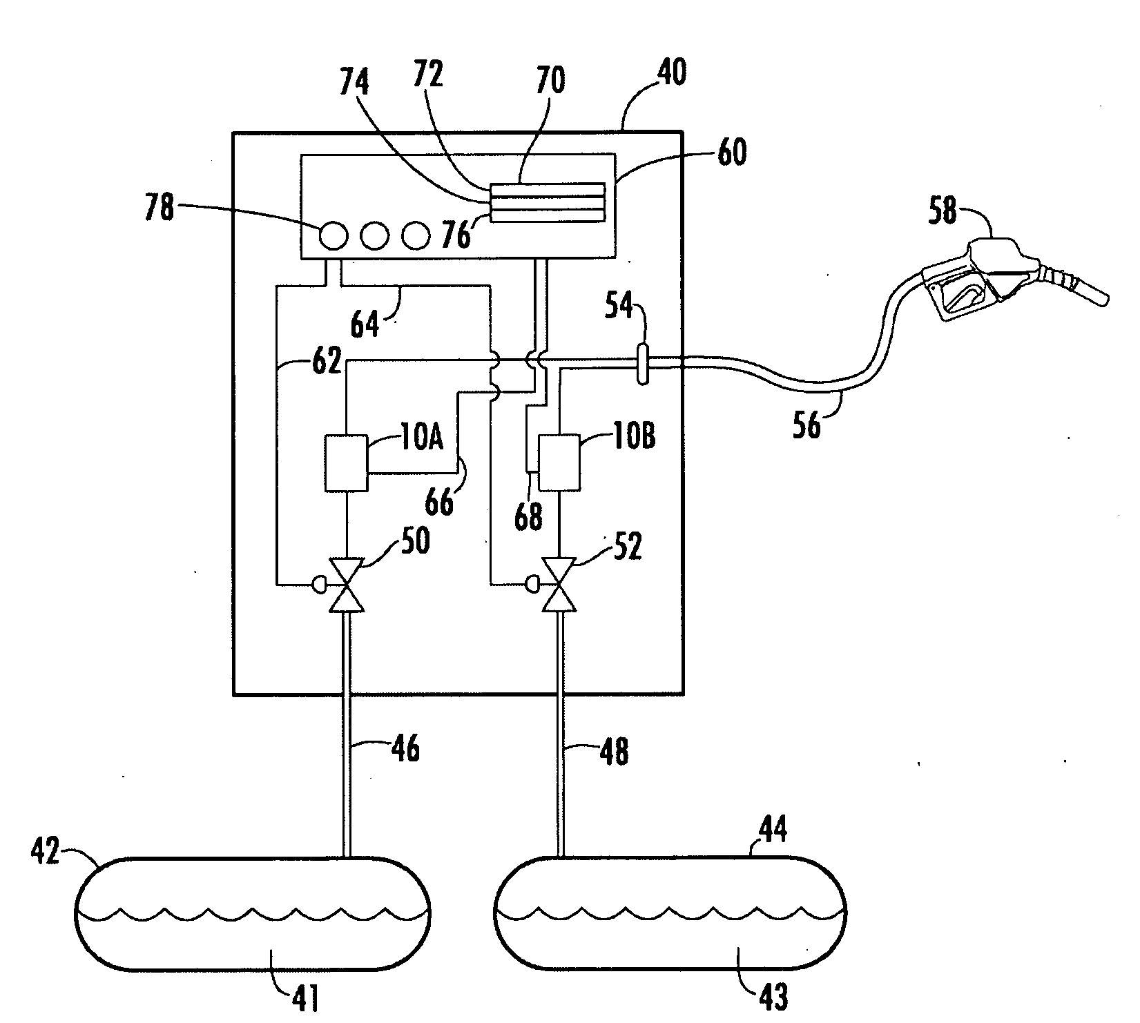
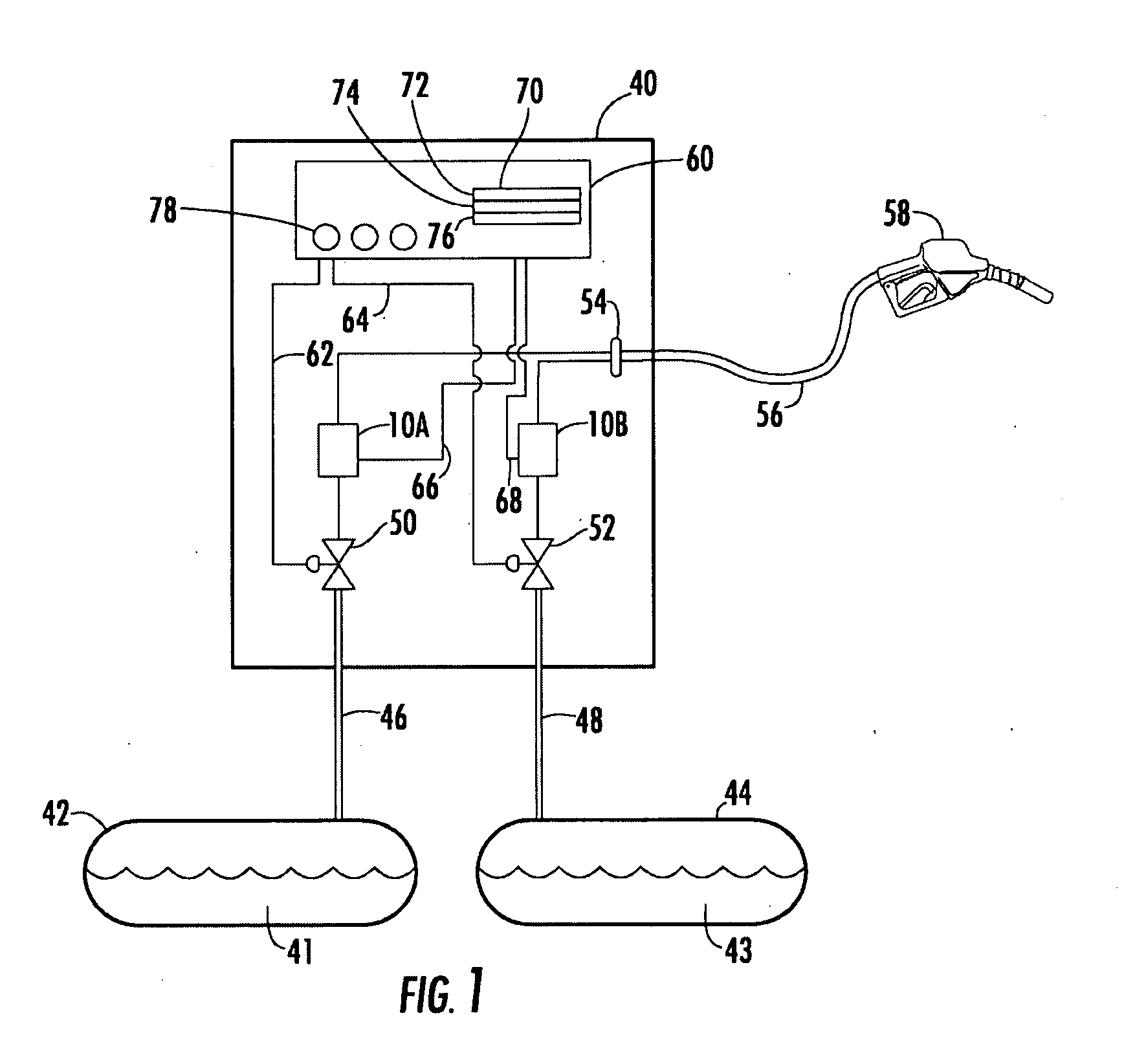
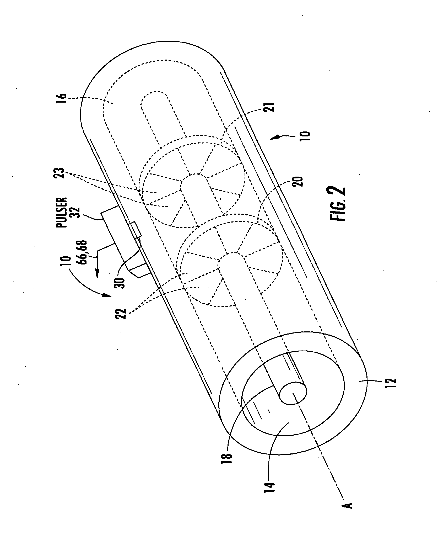
[0025]FIG. 1 illustrates a pair of turbine flow meters 10A and 10B utilized in a fuel dispenser 40. As is well-known, a fuel dispenser such as fuel dispenser 40 is used to dispense and measure the amount of fuel being delivered to a vehicle (not shown). Accurate meters are required to measure fuel dispensing to comply with Weights & Measures regulatory requirements.

[0026]Fuel dispenser 40 may be a blending type fuel dispenser wherein a low-octane fuel 41 stored in a low-octane underground storage tank (UST) 42 and a high-octane fuel 43 stored in a high-octane underground storage tank (UST) 44 are blended together by fuel dispenser 40 to deliver either a low-octane fuel 41, high-octane fuel 43, or a mixt...


PUM


Abstract

An apparatus and method for measuring fluid flow comprising an inferential flow meter having a housing defining a fluid flow path. A pulser is operative to produce an output signal indicative of flow rate through the meter. The apparatus further includes a controller in electronic communication with the pulser so as to receive the output signal. Based on the output signal, the controller is operative to determine fluid flow in a plurality of dynamic time sub-windows corresponding to respective periods of substantially consistent instantaneous flow.

Description

BACKGROUND OF THE INVENTION[0001]The present invention relates generally to flow meters for use in fuel dispensing environments. More particularly, the invention relates to an inferential flow meter adapted to have enhanced accuracy when pulsations occur in the flow.[0002]Inferential flow meters, e.g., a turbine flow meter, may be used in a variety of applications in fuel dispensing environments. For example, turbine flow meters are often used to meter fuel being dispensed, measure the vapor being returned to the underground storage tank in a stage two vapor recovery fuel dispenser, or measure the vapor or air released to atmosphere from the ullage area of an underground storage tank when a pressure relief valve in a vent stack is opened to relieve pressure.[0003]Turbine flow meters generally comprise a housing having inlet and outlet ports at respective ends thereof. A shaft is located inside the housing along the housing's longitudinal axis. One or more turbine rotors mounted on t...

Claims


Application Information

Patent Timeline
IPC IPC(8): B67D7/16G01F1/06B67D7/22
CPCB67D7/20G01F1/125G01F1/115
Inventor CARAPELLI, GIOVANNI
Owner GILBARCO ITAL SRL
Why Eureka
Try Eureka