
Dual drainage pathway shunt device

a shunt device and dual-channel technology, applied in the field of glaucoma surgery, can solve the problems that the schlemm's canal may not provide adequate drainage in some patients, and the shunt may not be suitable for all patients, and achieve the effect of improving the shunt size and reducing the shunt siz

Inactive Publication Date: 2010-09-16
GLAUKOS CORP
View PDF14 Cites 36 Cited by
  • Summary
  • Abstract
  • Description
  • Claims
  • Application Information

AI Technical Summary

Benefits of technology

This approach minimizes scarring, reduces the risk of hypotony and infection, and provides a more sustainable reduction in intraocular pressure by utilizing the eye's natural drainage systems, potentially leading to longer-lasting pressure control and improved patient outcomes.

Problems solved by technology

While the use of Schlemm's canal as a drainage pathway for glaucoma patients appears feasible, clinical studies have shown that a single device draining from the anterior chamber solely into Schlemm's canal may not provide adequate drainage in some patients to reduce pressures to acceptable levels.
Further, when pressures are decreased after surgery, in some patients they may begin to increase again at an unpredictable time in the future.

Method used


Image

  • Dual drainage pathway shunt device
  • Dual drainage pathway shunt device
  • Dual drainage pathway shunt device

Examples


Embodiment Construction

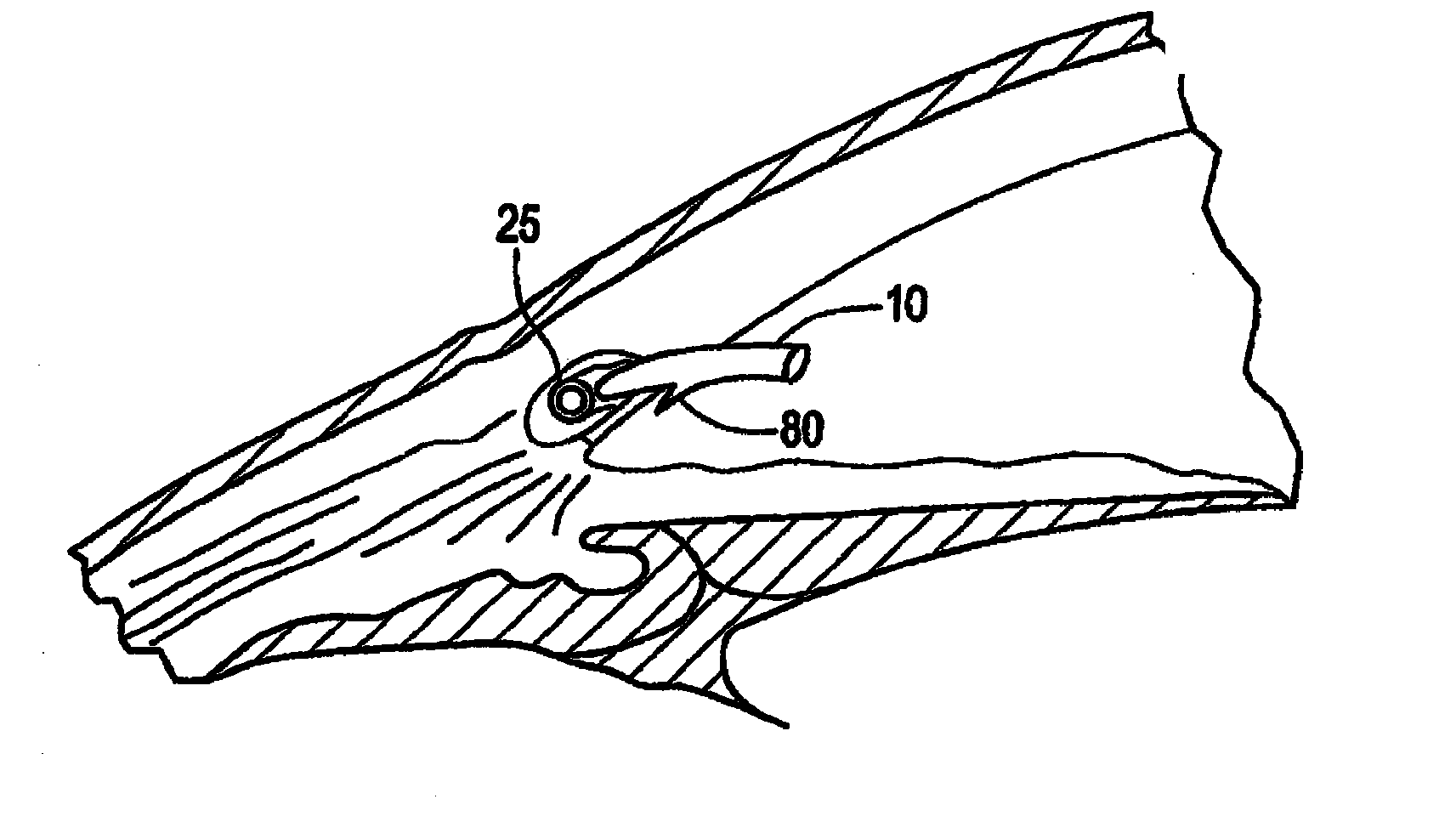
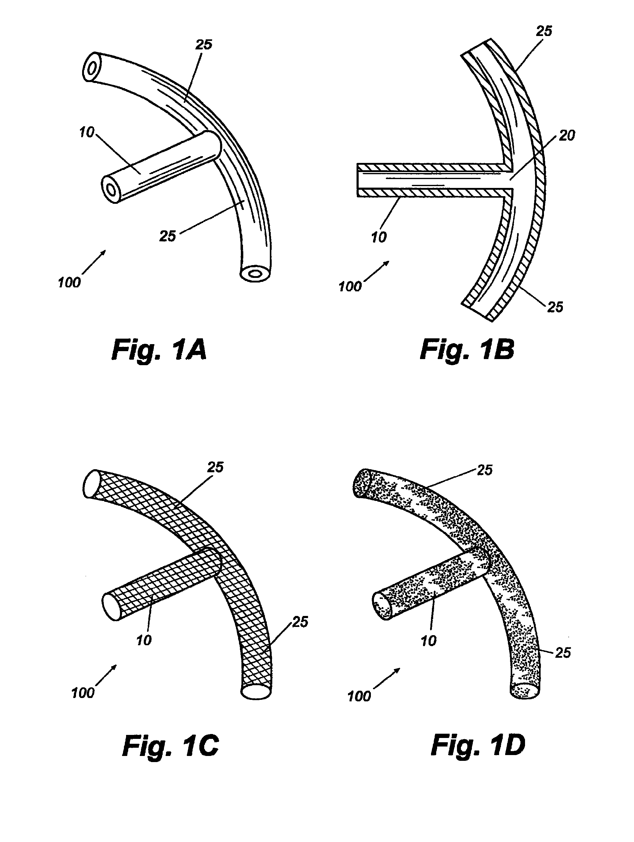
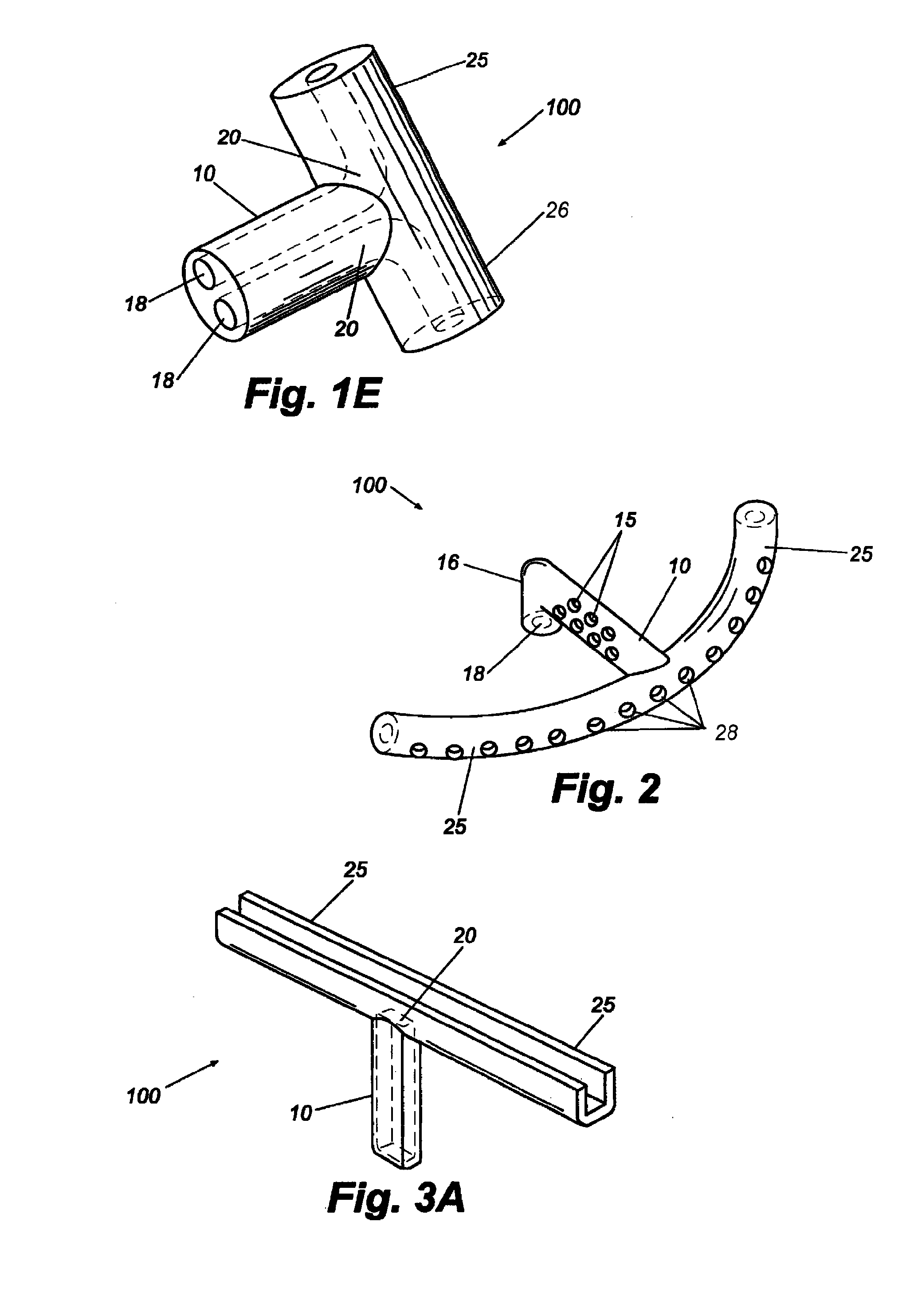
[0073]The present invention provides aqueous humor shunt devices to divert aqueous humor in the eye from both the anterior chamber into Schlemm's canal and a second anatomical space in the eye. The shunt devices can comprise a first distal portion having a terminal aspect sized and shaped to be received within a portion of Schlemm's canal, a second distal portion sized and shaped to be received with a second anatomical space in the eye and a proximal portion having at least one terminal aspect sized and shaped to be received within the anterior chamber of the eye, wherein the device permits fluid communication between the proximal portion in the anterior chamber to the distal portions in Schlemm's canal and the second anatomical space. Fluid communication can be facilitated by an aqueous humor directing channel in either the proximal or distal portions, as described below. Fluid communication can also be facilitated by the use of a seton, or other porous, wick-like components at the...


PUM


Abstract

A shunt is provided for the flow of aqueous humor from the anterior chamber of the eye to Schlemm's canal and to other anatomical spaces of the eye. The shunt comprises at least one lumen and optionally has at least one anchor extending from a proximal portion of the shunt to assist in placement and anchoring of the device in the correct anatomic position.

Description

CROSS-REFERENCE TO RELATED APPLICATIONS[0001]This application is a divisional of U.S. application Ser. No. 11 / 742,484, filed on Apr. 30, 2007, which claims priority under 35 U.S.C. §119(e) to U.S. Provisional Application No. 60 / 796,424, filed on May 1, 2006, the disclosure of each of which is incorporated by reference herein in its entirety. This application also cross references U.S. application Ser. No. 10 / 899,687, filed Jul. 27, 2004, now U.S. Pat. No. 7,220,238, which is a continuation of U.S. application Ser. No. 10 / 222,209, filed Aug. 16, 2002, which a) claims priority under 35 U.S.C. §119(e) to U.S. Provisional Application Ser. No. 60 / 312,799, filed Aug. 16, 2001 and b) is a Continuation-In-Part of U.S. application Ser. No. 09 / 558,505, filed Apr. 26, 2000, now U.S. Pat. No. 6,450,984, which claims priority under 35 U.S.C. §119(e) to U.S. Provisional Application No. 60 / 131,030, filed Apr. 26, 1999, all of which are incorporated in their entirety by reference herein.BACKGROUND ...

Claims


Application Information

Patent Timeline
Patent Type & Authority Applications(United States)
IPC IPC(8): A61M1/00
CPCA61F9/00781
Inventor LYNCH, MARY G.BROWN, REAY H.SMEETS, GUIDO
Owner GLAUKOS CORP
Learn More