Cutting aid for a motorized saw

a motorized saw and cutting aid technology, applied in the direction of metal sawing devices, metal sawing apparatuses, manufacturing tools, etc., can solve the problems of difficult to keep the cut moving in a straight line, inconvenient to use, and additional steps, so as to improve the building industry and quickly cut an object

Inactive Publication Date: 2010-09-23
HASSENBOEHLER JR CHARLES B
View PDF52 Cites 7 Cited by
  • Summary
  • Abstract
  • Description
  • Claims
  • Application Information

AI Technical Summary

Benefits of technology

[0002]Handheld, motorized cutting tools have greatly enhanced the building industry by providing an ability to quickly cut an object such as wood to a desired length. However, obtaining an accurate orthogonal or angled cut across an object relative to a lengthwise direction of the object while keeping the cut moving in a straight line has been difficult without first pre-marking the object with a reference line. Marking the object requires additional steps and tools that may not always be readily available to the use or convenient for the user to use.
[0004]Accordingly, what is needed is a cutting aid that simplifies blade path and angular directional alignment of the cutting tool and enables a user to quickly align and maintain a substantially linear cutting plane across a width of an elongated object to be cut.
[0006]The motorized saw may include, for example, a rotary saw or a reciprocating saw. One embodiment including a rotary saw further includes a second groove interrupting the primary engagement surface, the second groove extending from a first edge of the shoe to a second edge of the shoe, and configured for engaging an elongate edge of an object to be cut by the motorized saw, thereby assisting in providing a cut substantially orthogonal to an upper surface of said object when the motorized saw is rotated about the second groove to begin cutting said object. A specific embodiment includes a shoe configuration wherein the first groove is located along the shoe at a first position relative to the blade and wherein the second groove is oriented substantially orthogonal to the cutting plane of the blade and located along the shoe at a second position relative to the blade and spaced-apart from the first position so that the first and second grooves are adjacent to opposite ends of the shoe.
[0007]In a preferred embodiment, the rotary saw version includes a guide means for assisting a user in maintaining the directional alignment of a cut once cutting has begun using the rotary saw. In one particular embodiment the guide means includes an axle, a first non-slip wheel fixedly attached adjacent a proximal end of the axle, and a second non-slip wheel fixedly attached adjacent a distal end of the axle, the axle being rotatably attached to the shoe in an orientation orthogonal to the cutting plane of the blade, whereby the guide means helps to maintain the direction of a cut made by the motorized saw in the object. In a related embodiment, the guide means includes a light emitting apparatus attached adjacent the blade, the light emitting apparatus for projecting a light beam along a desired cutting path superimposed substantially along the cutting plane. A specific embodiment including the light emitting apparatus further includes an optical diversion structure for diverting at least a portion of the light beam from the light emitting apparatus along a desired reference path, wherein the reference path is oriented at an angle relative to the desired cutting path, the angle ranging from about 0 degrees to about 175 degrees. In yet another related embodiment, the guide means includes a blade plane indicator extending from a front edge of a blade guard such that the blade indicator is oriented along the cutting plane of the blade.
[0008]In another embodiment, the rotary saw version includes a detent oriented at an angle ranging from about 0 degrees to about 60 degrees relative to the orientation of the first groove, the detent configured for engaging an elongate edge of said object to be cut by the motorized saw, thereby assisting in providing an angled cut relative to said elongate edge of said object when the motorized saw is rotated about the detent to begin cutting said object.

Problems solved by technology

However, obtaining an accurate orthogonal or angled cut across an object relative to a lengthwise direction of the object while keeping the cut moving in a straight line has been difficult without first pre-marking the object with a reference line.
Marking the object requires additional steps and tools that may not always be readily available to the use or convenient for the user to use.
While edge guides and other devices may be attached to handheld motorized cutting tools, these devices are not suitable for guiding the cutting tool when the object to be cut has a cutting plane that is too far from a guiding edge to use the guide to maintain a precise cut.

Method used


Image

  • Cutting aid for a motorized saw
  • Cutting aid for a motorized saw
  • Cutting aid for a motorized saw

Examples


first embodiment

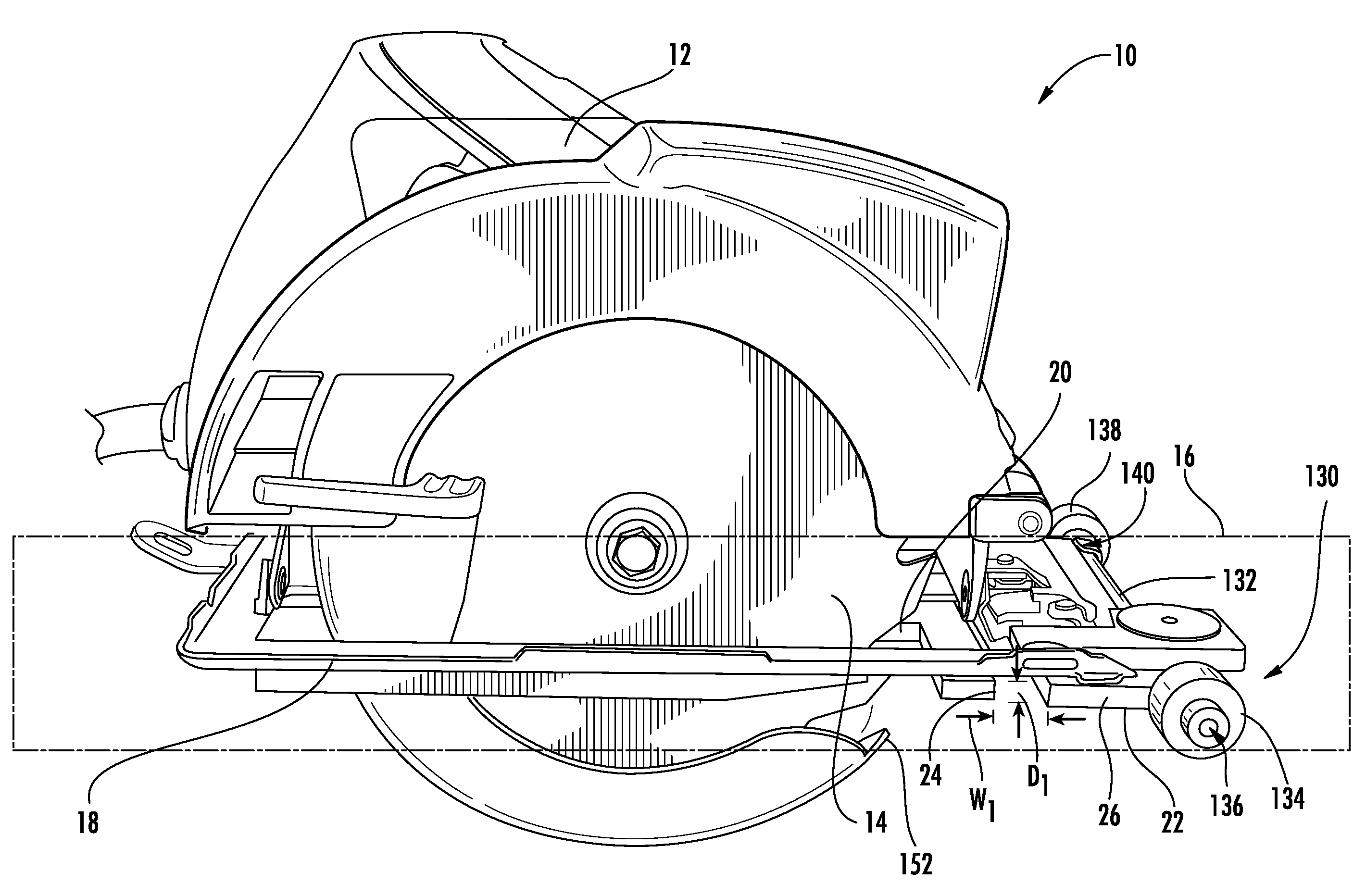
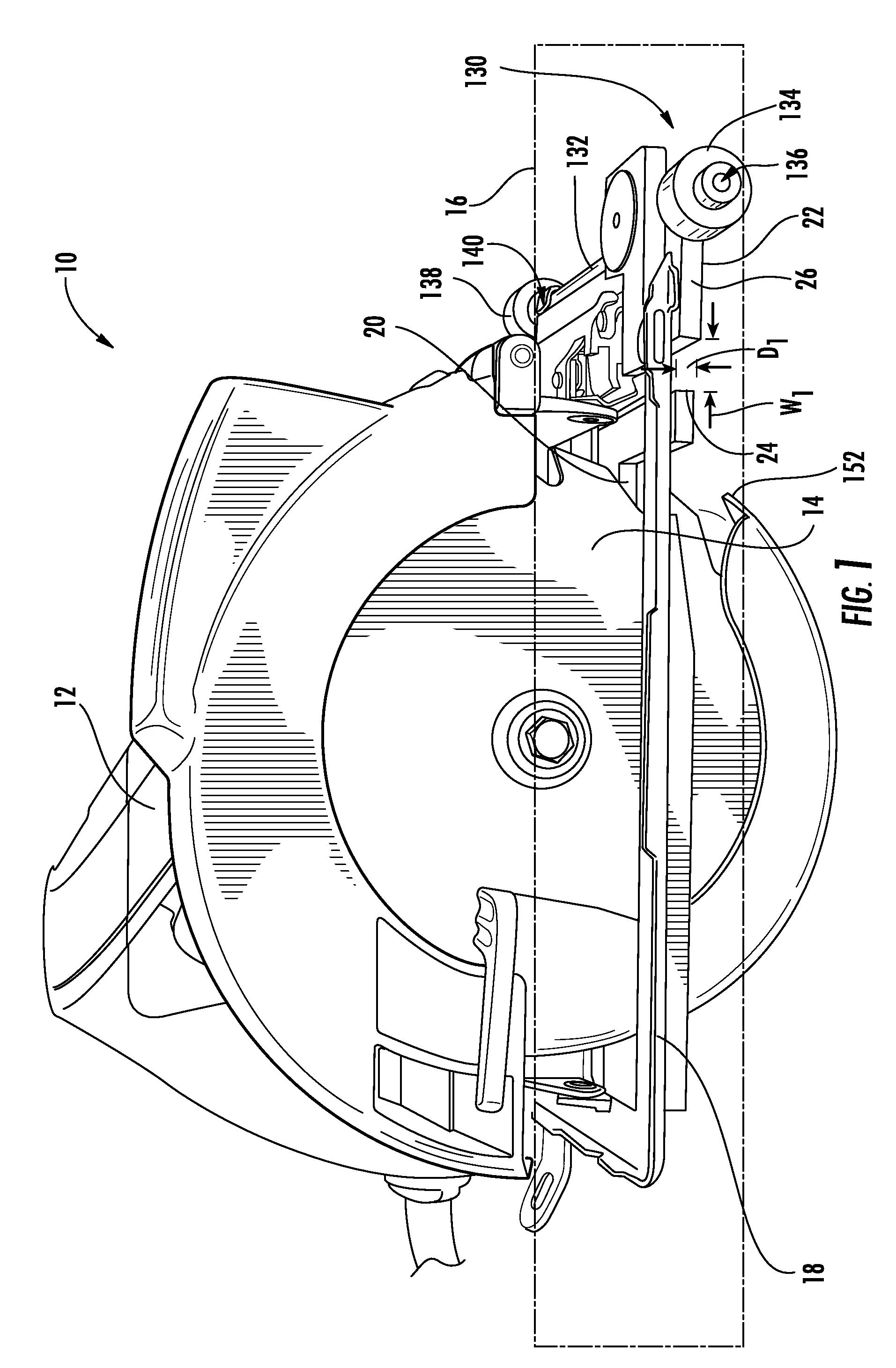
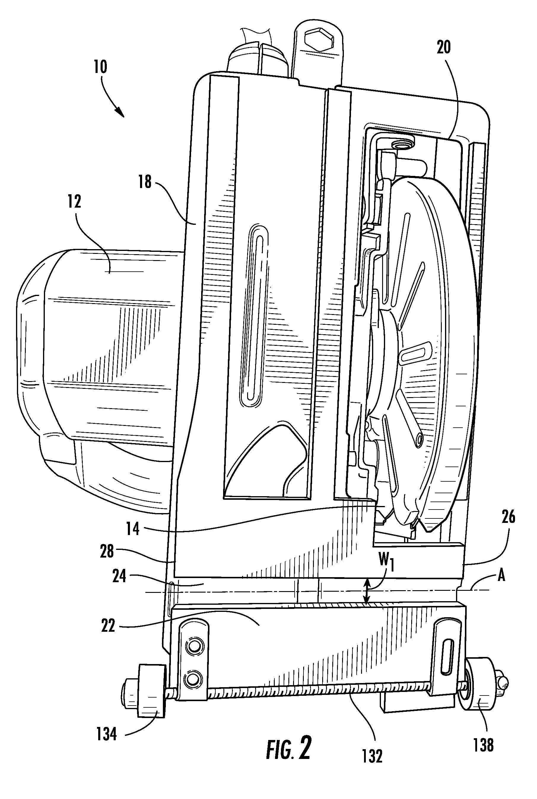
[0046]FIGS. 1-7 show a motorized saw 10 including a motor 12, a blade 14 defining a cutting plane 16, and a shoe 18 for holding the blade 14 of the motorized saw 10 in a predetermined relationship to an object to be cut. The motorized saw 10 in FIGS. 1-7 is illustrated as a rotary electric saw, but other types of motorized saws are contemplated by the disclosure. In the embodiment shown in FIGS. 1-7, the blade 14 is rotatably engaged with the motor 12 and removably attached adjacent thereto. The shoe 18 is attached adjacent the motor 12, the shoe 18 including an aperture 20 through which the blade 14 extends, a primary engagement surface 22 for engaging a surface of an object to be cut, and a first groove 24 interrupting the primary engagement surface 22.

[0047]The first groove 24 in the shoe 18 is oriented substantially orthogonal to the cutting plane 16 and extends from a first edge 26 of the shoe 18 to a second edge 28 of the shoe 18. The first groove 24 is configured for engaging...

second embodiment

[0049]FIGS. 9-10 show a motorized saw including a reciprocating motorized saw 30. The reciprocating motorized saw 30 further includes a motor (not shown) capable of producing a reciprocating motion, a blade 34 defining a cutting plane 36, and a shoe 38. The blade 34 is removably engaged with the motor and removably attached adjacent thereto. The shoe 38 is attached adjacent the motor, the shoe 38 including an aperture 40 through which the blade extends, a primary engagement surface 42 for engaging an object to be cut, and a first groove 44 interrupting the primary engagement surface 42.

[0050]The first groove 44 is oriented substantially orthogonal to the cutting plane 36 and extends from a first edge 46 of the shoe 38 to a second edge 48 of the shoe 38. The first groove 44 is configured for engaging an elongate surface or edge of an object to be cut by the motorized saw 30. After the first groove 44 is engaged with the elongate edge of the object to be cut, the motorized saw 30 may ...

fifth embodiment

[0058]a motorized rotary saw 102 shown in FIGS. 16-17 includes a protruding detent 104. The motorized saw 102 in FIGS. 16-17 does not include a fixed groove, however. Rather, the detent 104 extends outward from a bottom surface 106 of a shoe 108 to assist a user in initially aligning an elongate edge of an object to be cut at a desired angle relative to the cutting plane 16 of the blade 14. The detent 104 is oriented at an angle ranging from about 90 degrees to about 150 degrees relative to the cutting plane 16. The detent 104 is located near a first interface point 110 defined by the location at or near where the blade 14 and the object being cut initially make contact. In order to help balance the contact between the motorized saw 102 and an object being cut, the saw 102 further includes one or more shoe spacers 112. The detent 104 of the rotary saw 102 shown in FIGS. 16-17 is movable; however other embodiments may include a stationary detent(s).

[0059]In a related embodiment shown...


PUM

PropertyMeasurementUnit
depthaaaaaaaaaa
angleaaaaaaaaaa
angleaaaaaaaaaa

Abstract

A motorized saw including a specially designed shoe for performing more precise cuts without the necessity of making line marks on a target object is disclosed. The motorized saw may be in different forms including a rotary saw and a reciprocal saw. A motorized rotary saw modification member is also disclosed which includes a substantially planar base for attachment to the shoe of a rotary saw. The base further includes an aperture through which a blade may extend, a primary engagement surface for engaging an object to be cut, a leading edge, a plurality of fastening members for removably attaching the modification member to the shoe of a rotary saw, and a first detent interrupting the primary engagement surface, oriented at an angle ranging from about 0 degrees to about 60 degrees relative to the leading edge.

Description

TECHNICAL FIELD[0001]The disclosure relates to the field of cutting apparatuses and accessories therefor and in particular to aids for improving the use of handheld cutting devices.BACKGROUND AND SUMMARY[0002]Handheld, motorized cutting tools have greatly enhanced the building industry by providing an ability to quickly cut an object such as wood to a desired length. However, obtaining an accurate orthogonal or angled cut across an object relative to a lengthwise direction of the object while keeping the cut moving in a straight line has been difficult without first pre-marking the object with a reference line. Marking the object requires additional steps and tools that may not always be readily available to the use or convenient for the user to use.[0003]For example, a user may have the object to be cut and the motorized cutting tool ready to cut the object, but before cutting the user has to locate a marking tool and a tool such as a square to inscribe or mark a line of a desired ...

Claims


Application Information

Patent Timeline
Patent Type & Authority Applications(United States)
IPC IPC(8): B26D7/00B26D1/12
CPCB23D51/02B27B9/04B27B9/00Y10T83/828Y10T83/9372Y10T83/7734
Inventor HASSENBOEHLER, JR., CHARLES B.
Owner HASSENBOEHLER JR CHARLES B
Why Eureka
Try Eureka