Apparatus for reducing drag on a nautical vessel

Inactive Publication Date: 2010-09-23
COSTAS DAN NICOLAUS
View PDF30 Cites 22 Cited by
  • Summary
  • Abstract
  • Description
  • Claims
  • Application Information

AI Technical Summary

Benefits of technology

[0013]To minimize the limitations in the prior art, and to minimize other limitations that will become apparent upon reading and understanding the present specification, the pre

Problems solved by technology

Due to the large hull surfaces that need to be covered, large amounts of air need to be provided to the bottom of the ship.
In these experiments, the bubbles were active injections and had a power penalty.
Moreover, they were only effective near the point of injection because they did not remain within the boundary layer close to the hull.
In the NMRI full-scale tests they also degraded the efficiency of propellers.
For example, U.S. Pat. No. 5,524,568, issued to Bobst, discloses a boat hull that “creates a layer or film of bubbles adjacent the submerged region of a boat hull by releasing a flow of air at numerous spaced apart locations on that region of the hull.” However, the Bobst invention requires the use of an air compressor pump, which takes energy and greatly reduces or even completely offsets the energy savings achieved by the effect of the bubbles.
Unfortunately, the standard air compressors, while able to deliver air at high pressure, are very, very inefficient at delivering the high volumes of air needed for covering the large bottom surfaces of a flat bottomed vessel.
Moreover, the energy economy obtained by the lubrication is largely offset by the air compressor's fuel consumption, rendering this solution essentially useless.
The problem with U.S. Pat. No. 6,748,891 and other similar references, is that the small pressure differentials created work only for relatively small drafts.
Additionally, regarding the combi

Method used


Image

  • Apparatus for reducing drag on a nautical vessel
  • Apparatus for reducing drag on a nautical vessel
  • Apparatus for reducing drag on a nautical vessel

Examples


Example

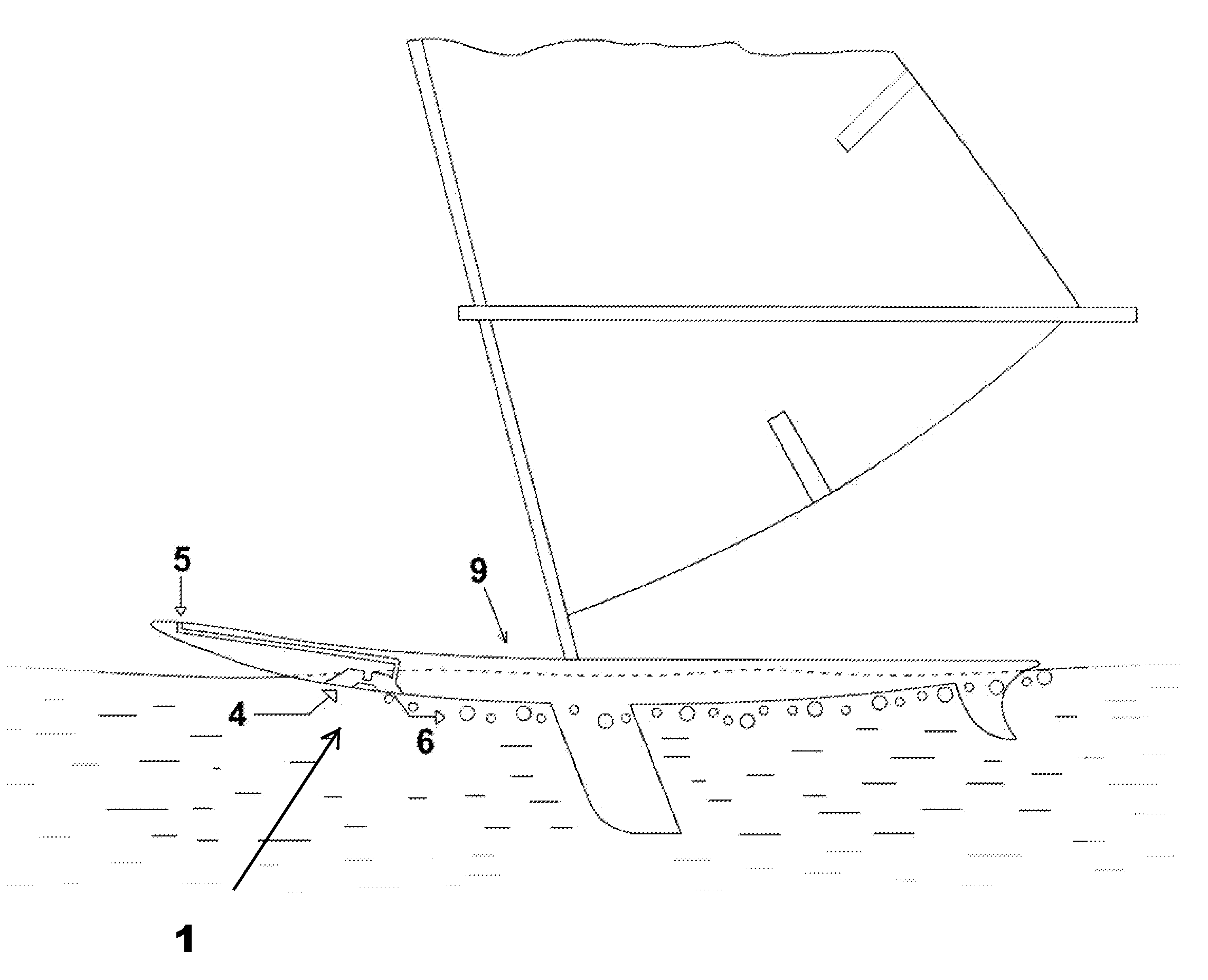
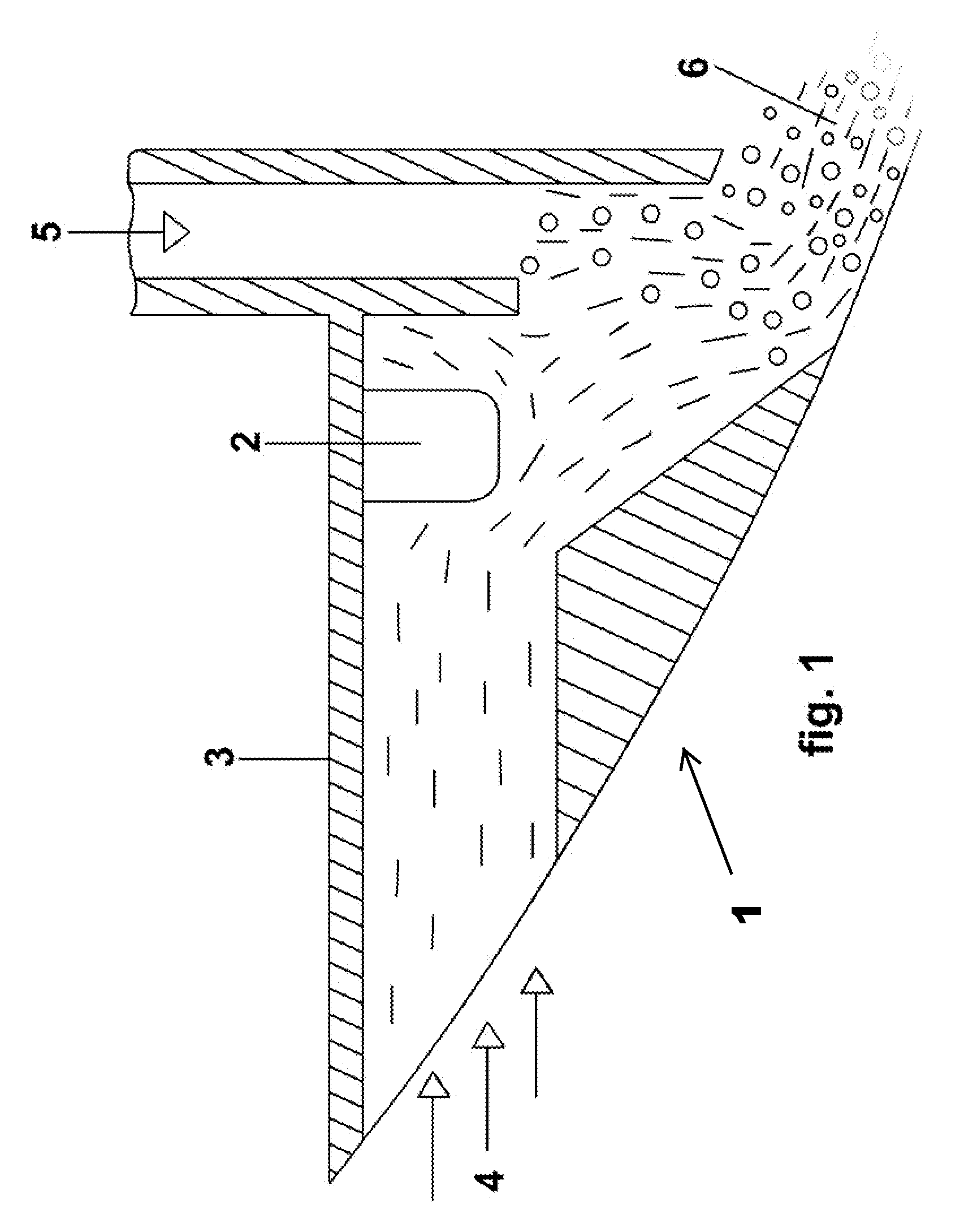
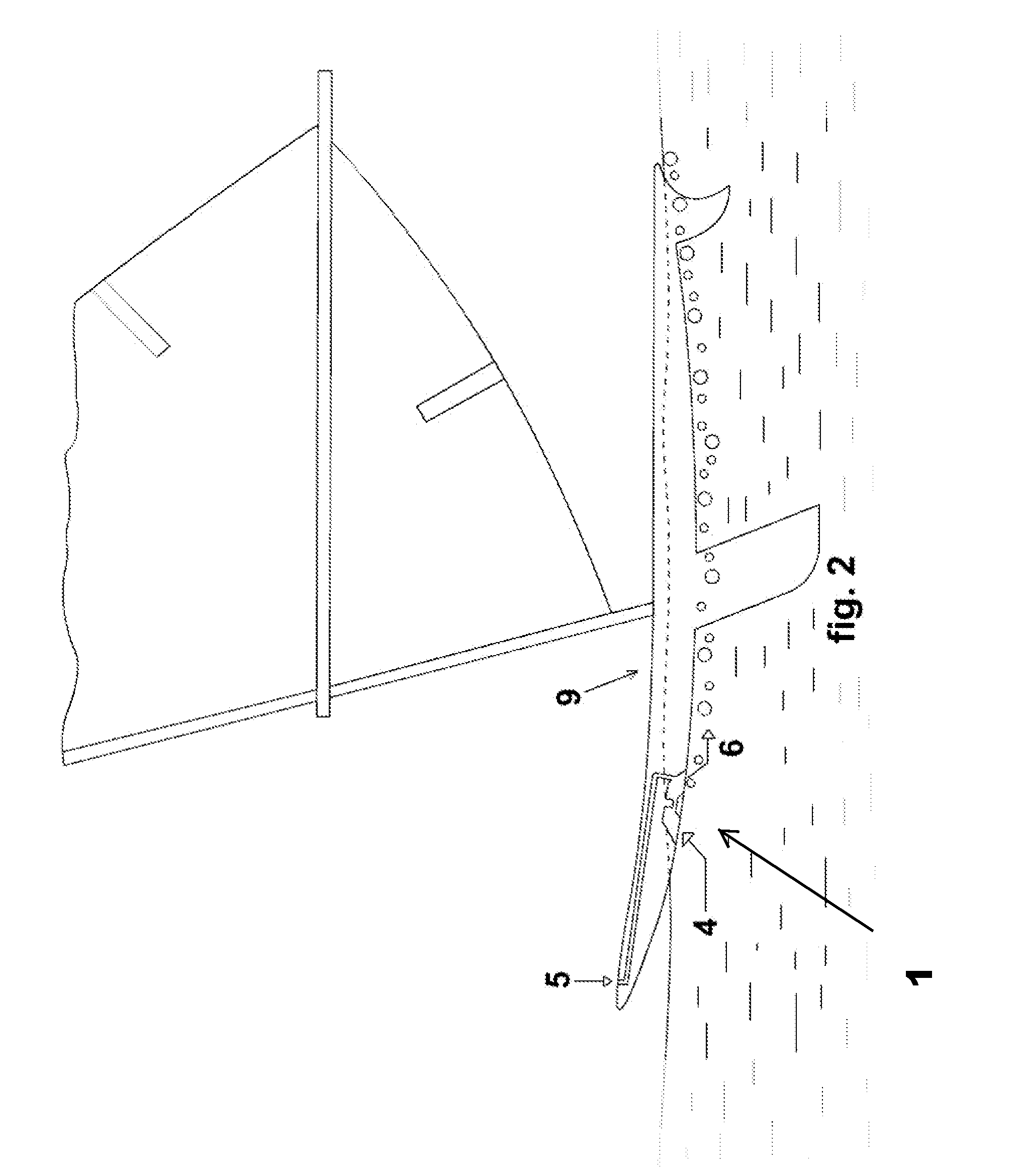
DETAILED DESCRIPTION OF THE DRAWINGS

[0048]In the following detailed description of various embodiments of the invention, numerous specific details are set forth in order to provide a thorough understanding of various aspects of one or more embodiments of the invention. However, one or more embodiments of the invention may be practiced without some or all of these specific details. In other instances, well-known methods, procedures, and / or components have not been described in detail so as not to unnecessarily obscure aspects of embodiments of the invention.

[0049]While multiple embodiments are disclosed, still other embodiments of the present invention will become apparent to those skilled in the art from the following detailed description, which shows and describes illustrative embodiments of the invention. As will be realized, the invention is capable of modifications in various obvious aspects, all without departing from the spirit and scope of the present invention. Accordingly, ...


PUM


Abstract

The invention is an apparatus and method for reducing the drag that a vessel hull experiences when moving through the water by interposing air bubbles between the skin of the hull and the stream of water that the vessel is moving through. The invention delivers compressed air to the bottom of the vessel without the need for a high energy air compressor.

Description

CROSS-REFERENCE TO RELATED APPLICATIONS[0001]Priority is claimed to U.S. Provisional Patent Application Ser. No. 61 / 210,685, filed on Mar. 23, 2009, titled “Method and Systems for Naval Drag Reduction (Modular),” by inventor Dan Nicolaus Costas, the contents of which are expressly incorporated herein by this reference.FIELD OF INVENTION[0002]This invention relates to the method and apparatus for drag reduction by interposing air bubbles between the skin of the hull of a nautical vessel and the stream of water that the vessel is moving through. More particularly, the invention relates to a method and apparatus of interposing the air bubbles without the need of an air compressor or other external high energy source.BACKGROUND[0003]For years, nautical vessel makers have been aware that placing air bubbles on the bottom of a vessel hull will reduce the drag of the vessel as it passes through water. The challenge as been how to efficiently place the air bubbles on the bottom of the hull....

Claims


Application Information

Patent Timeline
IPC IPC(8): B63B1/38B63B1/32
CPCY02T70/122B63B1/38Y02T70/10
Inventor COSTAS, DAN NICOLAUS
Owner COSTAS DAN NICOLAUS
Why Eureka
Try Eureka