Solar roofing system

a solar panel and roof technology, applied in the field of solar panels, can solve the problems of compromising the water tightness of the roof system, requiring structural upgrades to the building, and requiring the installation of solar panels with solar panels, etc., and achieve the effect of simple installation and cost-effectiveness

Active Publication Date: 2010-09-23
GARLAND INDS
View PDF19 Cites 50 Cited by
  • Summary
  • Abstract
  • Description
  • Claims
  • Application Information

AI Technical Summary

Benefits of technology

[0008]The present invention relates a connection arrangement to attach solar panels to a roofing system a building or other type of structure. More particularly, the invention relates to a connection arrangement and method for attaching one or more solar panels (e.g., photovoltaic panels) to the surface of a roofing system of a building or other type of structure. The connection arrangement of the present invention that is used to attach solar panels to the roofing system is designed to be used with metal roofing systems (e.g., standing seam metal roofing system, etc.). Indeed, the connection arrangement of the present invention can be used to attach many different types of solar panels to many different types of commercial and residential metal roof systems. The connection arrangement of the present invention can be used to attach many different types of solar panels (e.g., framed solar panels, thin film and flexible solar panels, etc.) to the siding system. Indeed, the connection arrangement of the present invention can be used to attach most, if not all, types solar panels to a roofing. The connection arrangement of the present invention is not dependent on the type of solar panel, the configuration of the solar panel, or the materials used to form the solar panel. The connection arrangement of the present invention used to attach solar panels to a roofing system of a building or other type of structure is designed to 1) be durable, 2) be lightweight, 3) be useable in many different types of weather conditions encountered by such systems, 4) require little or no modifications to the structure of an existing roofing system of a building or other type of structure, 5) be cost effective, and / or 6) be simple to install.
[0019]One non-limiting object of the present invention is to provide an improved connection arrangement between a roofing system and a solar panel.
[0023]In still yet another and / or alternative aspect of the present invention is to connected solar panels to a roof of a building or other type of structure without having to reinforce the roof of the building or other type of structure.

Problems solved by technology

Furthermore, such solar panel systems typically require separate support structures that are typically bolted together to form an array of larger solar panels.
The mounting arrays for such solar panels can require structural upgrades to the building due to added weight of the support structures and the solar panels.
Additionally, these traditional mechanical arrangements for securing the solar panels to the roofing system require the forming of holes in the roof system surface and / or other modifications to the surface of the roof system that can impair the integrity of the roof surface.
For instance, multiple penetrations of the roof membrane when installing the multiple solar panels can compromise the water-tightness of the roof system.
Consequently, the water resistant or repellant properties of the roof system can be impaired when installing solar panels on a roof system.
Furthermore, these mechanical connectors can become rusted and corroded overtime, thus becoming difficult to remove, thereby a) increasing the time and cost associated with the repair of the solar panel and / or b) increasing the incidence of damage to the solar panel, solar panel mounting arrangement and / or roofing system.
However, the use of ballast blocks adds significant weight to a roofing system, thus the use of ballast blocks cannot always be used on building structures when such building structures cannot support such added weight.
In addition, the use of ballast blocks cannot be used on sloped roof surfaces, thus limiting the use of such arrangements to flat roofing systems.
Although such a connection arrangement at first appearance may seem appealing, there are many questions concerning whether such a connection arrangement can properly and successfully secure solar roofing panels to a roof surface overtime, especially in wind prone regions or on a sloped roof system.

Method used


Image

  • Solar roofing system
  • Solar roofing system
  • Solar roofing system

Examples


Embodiment Construction

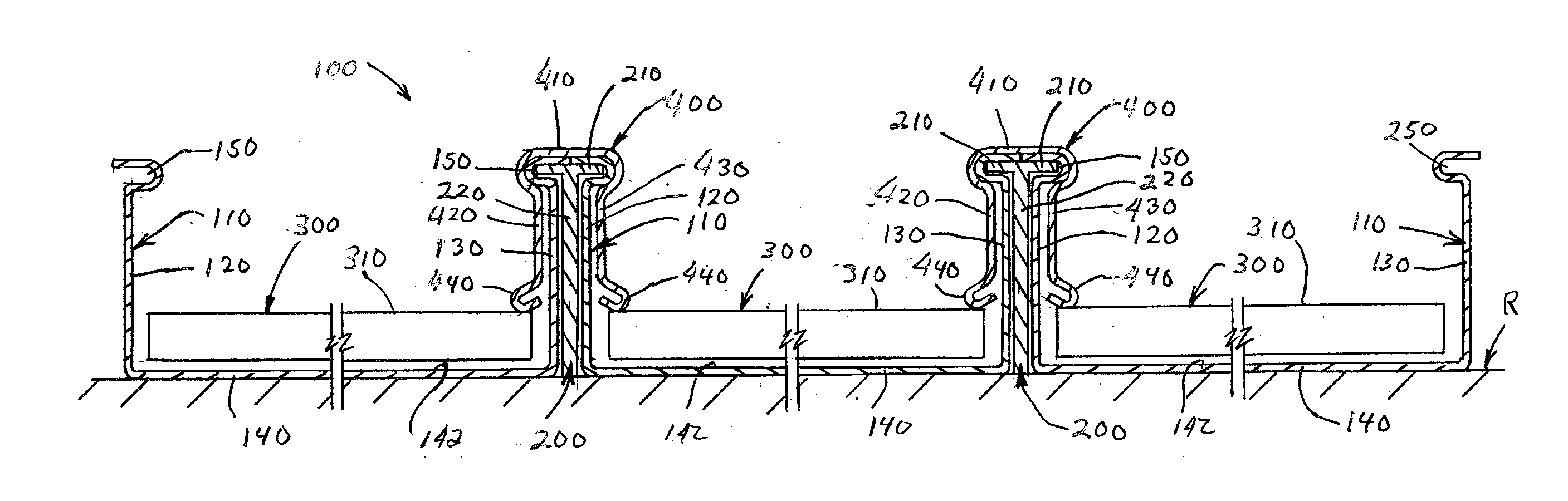
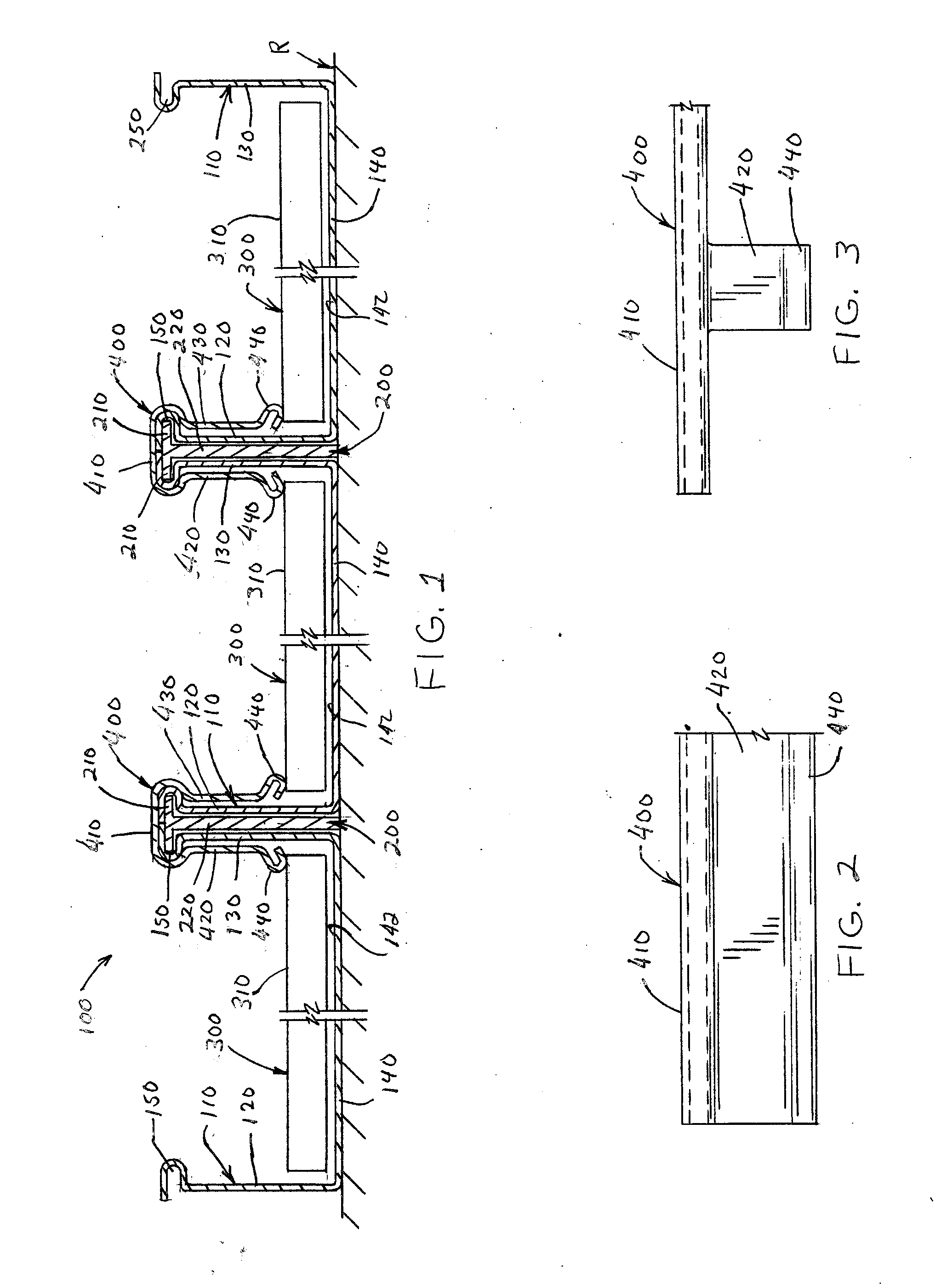
[0036]Referring now to the drawings wherein the showings are for the purpose of illustrating non-limiting embodiments of the invention only and not for the purpose of limiting same, FIG. 1 illustrates a roof panel system 100 that is formed of a plurality of roof panels 110. The roof panels are generally formed of a metal material; however, this is not required. The roof panels include two side flanges 120, 130 and a base section 140 connected therebetween. The base section and side flanges form a generally U-shaped cross-sectional profile for each of the roof panels; however, other profiles can be formed. As can be appreciated, the configuration of the roof panel, side flanges of the roof panel, and base section of the roof panels in non-limiting. As also can be appreciated, the material used to form the roof panel is non-limiting. The side flanges 120, 130 generally have a shorter length than the base portion; however, this is not required.

[0037]An anchoring clip 200 is illustrated...


PUM

PropertyMeasurementUnit
reflectivityaaaaaaaaaa

Abstract

An apparatus and method for connecting solar panels to a roof system surface. The solar panels can be formed flexible or non-flexible solar panels that are at least partially attached to a roofing surface by use of a fastener.

Description

[0001]The present invention claims priority on U.S. Provisional Application Ser. Nos. 61 / 187,415 filed Jun. 16, 2009; 61 / 184,984 filed Jun. 8, 2009; and 61 / 161,252 filed Mar. 18, 2009, all of which are incorporated herein by reference.FIELD OF THE INVENTION[0002]The present invention relates to solar panels, and generally to solar panels that can be connected to building structures.BACKGROUND OF THE INVENTION[0003]Rising energy costs, a public awareness to become more energy independent and environmentally friendly, and the reduction in the costs associated with solar panels has resulted in both consumers and commercial entities to consider retrofitting existing buildings with solar panels or to design new buildings that include solar panels. For instance, non-commercial and commercial owners and developers are increasingly considering alternative sources of energy to offset continued price increases of energy. As such, solar energy has received increased attention as an alternative...

Claims


Application Information

Patent Timeline
Patent Type & Authority Applications(United States)
IPC IPC(8): E04D13/18B23P15/26
CPCF24J2/045F24J2/5245F24J2002/4659F24J2002/4676Y02B10/12Y10T29/53Y02E10/44Y02E10/47H02S20/23Y10T29/53113Y02B10/20F24S20/67F24S25/61F24S2025/6001F24S2025/601Y02B10/10Y02E10/50
Inventor PIERSON, JOHN L.LAMBERT, BRIAN
Owner GARLAND INDS
Why Eureka
Try Eureka