Air Disk Brake Caliper Pre-Stressing Method and Pre-Stressed Caliper Apparatus

Active Publication Date: 2010-09-23
BENDIKS SPAJSER FAUNDEJSHN BREJK LLK
View PDF8 Cites 7 Cited by
  • Summary
  • Abstract
  • Description
  • Claims
  • Application Information

AI Technical Summary

Benefits of technology

[0025]The development of compressive forces around the plastically deformed portion of the cast iron brake caliper effectively shifts the load range Sr of the plastically-deformed portion of the caliper to a lower midrange stress on a Goodman diagram, similar to the shift in the FIG. 1 diagram from example A to example B. Thus, as a result of the inventive pre-stressing process, the most highly-stressed portion of the cast iron brake caliper sees lower peak stresses and lower midrange stresses, and the fatigue life of the caliper is increased, in some instances by two or more orders of magnitude. Moreover, because this process does not rely on surface treatments, it is capable of compressive pre-stressing of material wherever the region(s) of highest stress may be located, including within the internal structure of the cast iron brake caliper.
[0026]The inventive cast iron brake caliper pre-stressing process thus avoids the compromise solutions of the prior art. For example, there is no need for the use of costly higher strength materials to provide the required fatigue service life (and the associated increases in manufac

Problems solved by technology

These high performance brakes have not been widely adopted in U.S. commercial vehicles.
One impediment to wide-scale adoption of disk brakes in the U.S. is the relatively small wheel rims used on U.S. commercial vehicles, as compared those used in Europe, and U.S. vehicle operators' general reluctance to incur the expense of shifting to larger wheel rims, at least in the absence of a regulatory requirement to do so.
The Society of Automotive Engineers is leading work to establish a standard commercial vehicle brake packaging recommendation for industry-wide use, however, this effort has been ongoing for at least eight years without issuance of a formal standard or recommendation, and none is expected to be adopted as a regulatory requirement in the near future (the issuance of a government requirement being seen as a necessity to get commercial vehicle owners to move away from the current standard U.S. wheels).
None of these solutions has yet to provide a design without undesirable compromises, such as prohibitive cost (due to, for example, the use of higher strength, higher cost materials) or insufficient strength and/or fatigue life due to unacceptably thin caliper sections.
Engineering calculations and testing have sh

Method used


Image

  • Air Disk Brake Caliper Pre-Stressing Method and Pre-Stressed Caliper Apparatus
  • Air Disk Brake Caliper Pre-Stressing Method and Pre-Stressed Caliper Apparatus
  • Air Disk Brake Caliper Pre-Stressing Method and Pre-Stressed Caliper Apparatus

Examples


Example

DETAILED DESCRIPTION OF THE DRAWINGS

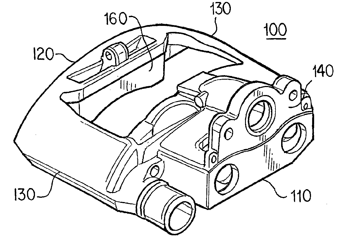
[0037]FIGS. 3a, 3b and 3c show an embodiment of a brake caliper 100 to which a pre-stressing process is to be applied. Because the basic design and operation of such calipers is well known to those of ordinary skill in the art, the majority of the components of a disk brake have been omitted from the figures for clarity.

[0038]FIG. 3a is an oblique view from above of caliper 100, which includes brake actuator side 110, reaction force side 120, and rotor bridging portions 130 which join the brake actuator side 110 and reaction side 120 over the outer radius of a brake rotor (not illustrated). As can be seen in FIG. 3b, which is a sectioned view of the brake actuator side 110 of the caliper 100 viewed from the reaction side, the bridging portions 130 directly over the rotor are among the thinnest portions of the caliper. As a result, these thin sections 130 are among the most highly stressed portions of the caliper when a brake application force is a...


PUM

PropertyMeasurementUnit
Forceaaaaaaaaaa
Forceaaaaaaaaaa
Forceaaaaaaaaaa

Abstract

A cast iron brake caliper with improved fatigue life, and a process and process equipment for pre-stressing a cast iron brake caliper to provide improved fatigue life, is provided. In the process, a load is applied to a cast iron caliper, where the load is high enough to locally yield and plastically deform the cast iron material, but not high enough to cause material failure, such as cracking. Upon load removal, residual compressive stresses in the cast iron caliper lower the mid-point of the stress range the plastically-deformed region of the caliper sees during in-service use, and thereby lowers the peak stress seen in this region, increasing fatigue life. The process permits a cast iron brake caliper to be designed to use less material and thus fit within constrained wheel rim envelopes, without the need to resort to high cost materials or other alternative design strategies.

Description

BACKGROUND OF THE INVENTION[0001]The present invention relates to brakes used on, for example, commercial truck or trailer axles, and in particular to manufacture of brake calipers used in such brakes.[0002]Air disk brakes have been widely adopted in Europe, primarily as result of their performance advantages over conventional drum brakes. These high performance brakes have not been widely adopted in U.S. commercial vehicles. One impediment to wide-scale adoption of disk brakes in the U.S. is the relatively small wheel rims used on U.S. commercial vehicles, as compared those used in Europe, and U.S. vehicle operators' general reluctance to incur the expense of shifting to larger wheel rims, at least in the absence of a regulatory requirement to do so.[0003]The Society of Automotive Engineers is leading work to establish a standard commercial vehicle brake packaging recommendation for industry-wide use, however, this effort has been ongoing for at least eight years without issuance o...

Claims


Application Information

Patent Timeline
IPC IPC(8): F16D55/00B23P15/00G01L5/28
CPCF16D2250/00Y10T29/49764F16D2250/0092Y10T29/53022Y10T29/49771F16D2200/0013F16D2055/0016F16D55/22B23P15/18B23P9/04
Inventor PLANTAN, RONALD S.LANTZ, JR., RICHARD L.
Owner BENDIKS SPAJSER FAUNDEJSHN BREJK LLK
Why Eureka
Try Eureka