
Utensil Storage Stand

a technology for utensils and storage stands, which is applied in the field of utensil storage, can solve the problems of limiting affecting the use of utensils, and affecting the use of utensils, and achieves the effects of convenient access and storage, convenient assembly and/or disassembly, and convenient compactness

Inactive Publication Date: 2010-09-23
CASS DAVID LEE +1
View PDF12 Cites 12 Cited by
  • Summary
  • Abstract
  • Description
  • Claims
  • Application Information

AI Technical Summary

Benefits of technology

[0017]It is an object of the present invention to provide a kitchen utensil stand that allows kitchen utensils to be easily stored and removed.
[0018]It is an object of the present invention to provide a kitchen utensil organizer that is compact and easily accessible.
[0021]It is a further object of the present invention to provide a utensil storage stand that will compactly store at least fifteen utensils at one time.
[0022]It is a further object of the present invention to provide a storage stand having open perforations and hooks for easy compact and convenient access and storage. It is an object of the present invention to provide an easy assembled and / or disassembled utensil storage stand, where the stand is comprised four individual pieces: a base, a column, and a disc and cylinder which forms a utensil engagement top.
[0023]It is an object of the present invention to provide a lightweight, compact utensil storage stand that may be disassembled into three pieces for shipping and cleaning purposes.TABLE OF NUMERICAL REFERENCES

Problems solved by technology

The open topped canister has the drawback of trapping and collecting dust and debris through its open top while also having the further disadvantage that the utensils may become tangled with one another and not easily withdrawn from the canister.
In addition if utensils are placed in the canister just after being washed they may drip some moisture into the bottom of the canister where it can accumulate and create unhealthy conditions.
Limited space on a countertop also limits the use of canisters because the utensils in the back of the canister are not easily accessible with the utensils in the front of the canister blocking an easy reach to the rear of the canister.
The canister or area that is usually available for the storage of utensils may be typically below the kitchen cabinets thereby limiting the space above the canister that is available to reach the utensils in the rear of the canister.
Utensil stands are known from which one may hang a utensil but either do not provide for rotation of the utensils or the compact storage of the utensils that are stored on the unit.
Hanging the utensils on known non-rotatable and non-compact stands takes up too much counter space and is not convenient to the user.

Method used


Image

  • Utensil Storage Stand
  • Utensil Storage Stand
  • Utensil Storage Stand

Examples


Embodiment Construction

[0037]In the following are detailed descriptions of the invention of exemplary embodiments. These embodiments are described in sufficient detail to enable those skilled in the art to practice the invention, but other embodiments may be utilized and logical, mechanical, electrical, and other changes may be made without departing from the scope of the present invention. The following detailed description is, therefore, not to be taken in a limiting sense, and the scope of the present invention is defined only by the appended claims.

[0038]In the following description, numerous specific details are set forth to provide a thorough understanding of the invention. However, it is understood that the invention may be practiced without these specific details. In other instances, well-known structures and techniques known to one of ordinary skill in the art have not been shown in detail in order not to obscure the invention.

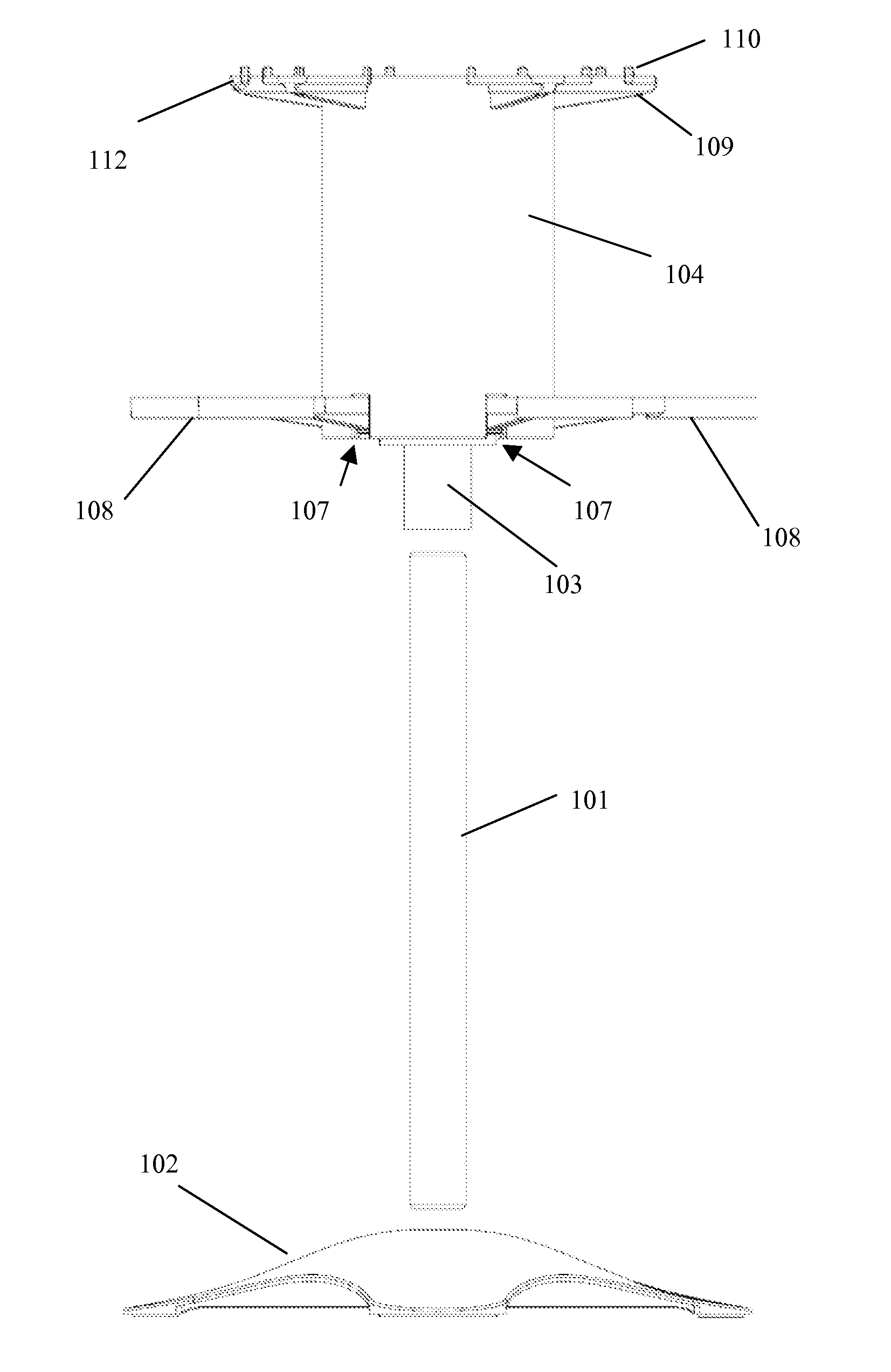
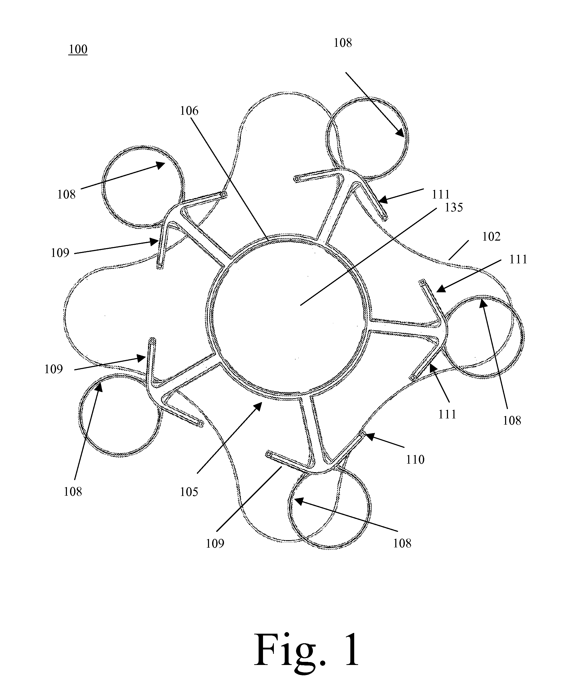
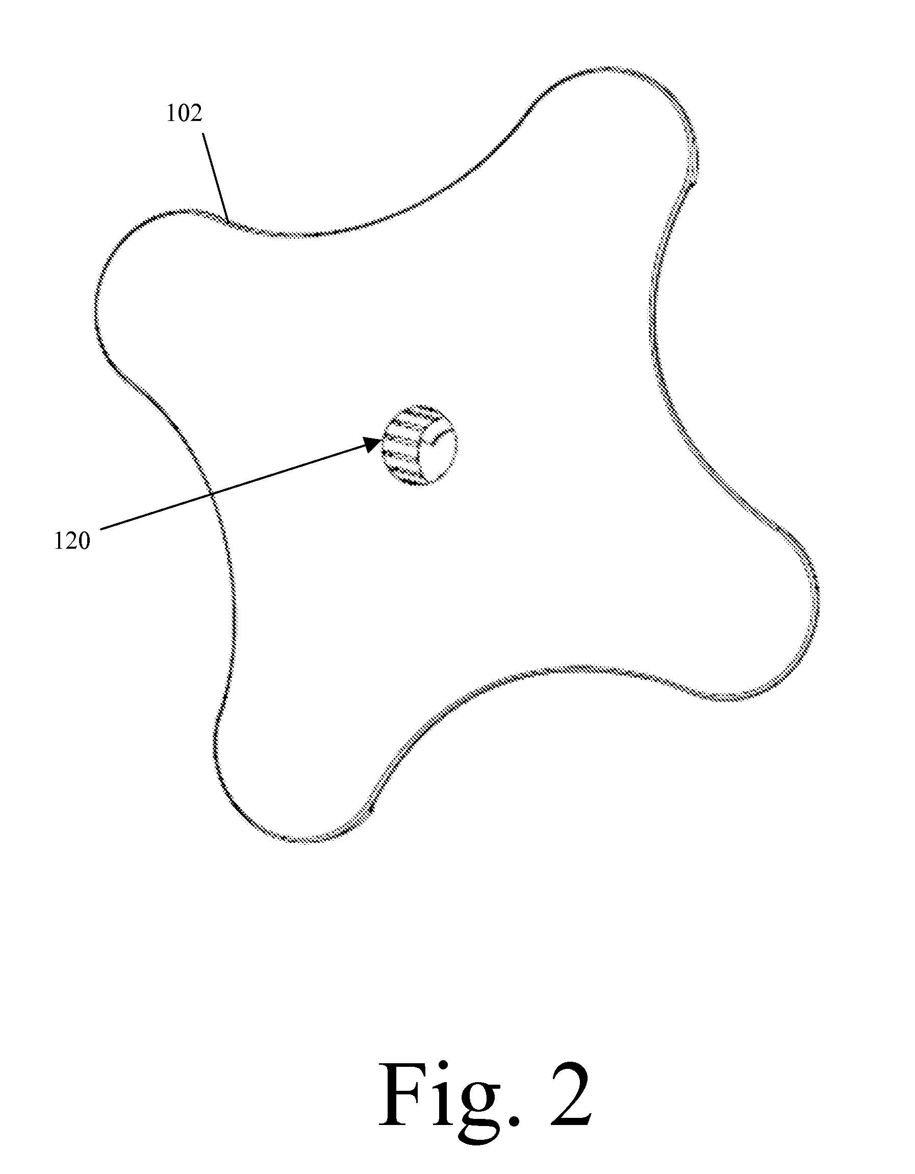
[0039]Referring now to the invention in more detail, in FIGS. 1 and 4 ...


PUM


Abstract

A utensil storage stand, which comprises a base, a column extending away from the base, a distal end on the column, and utensil engaging means rotatably mounted on the column. The utensil engaging means is rotatably mounted on the distal end of the column by a ball bearing arrangement comprising plastic races cooperating with plastic or ceramic bearings interposed between the races. The utensil engagement means comprises a first set of radially extending spokes with enlarged perforations through the spokes and a second set of radially extending spokes providing utensil support hooks extending from the spokes. The utensil engagement means is rotatably mounted with respect to column having an axis substantially perpendicular to the plane of the base. The open body of the utensil engagement means creates a canister for the purpose of containing small kitchen items with the disc top acting as the floor or bottom of the canister.

Description

CROSS REFERENCE TO RELATED APPLICATIONS[0001]This application is a continuation in part of U.S. patent application Ser. No. 12 / 383,207, entitled “Utensil Storage Stand”, filed on 20 Mar. 2009. The benefit under 35 USC §119(e) of the United States provisional application is hereby claimed, and the aforementioned application is hereby incorporated herein by reference.[0002]This application is related to U.S. patent application Ser. No. 29 / 108,107, entitled “Utensil Storage Stand”, filed on 8 Feb. 2008, now U.S. Pat. No. D595,996.[0003]This application is related to U.S. patent application Ser. No. 11 / 805,111, entitled “Utensil Storage Stand”, filed on 22 May 2007, now abandoned.FEDERALLY SPONSORED RESEARCH[0004]Not ApplicableSEQUENCE LISTING OR PROGRAM[0005]Not ApplicableTECHNICAL FIELD OF THE INVENTION[0006]The present invention relates generally to utensil storage. More specifically, the present invention relates to a utensil storage stand.BACKGROUND OF THE INVENTION[0007]Preparatio...

Claims


Application Information

Patent Timeline
Patent Type & Authority Applications(United States)
IPC IPC(8): A47J47/16
CPCA47J47/16
Inventor CASS, DAVID LEECASS, MARILYN KATHRYN
Owner CASS DAVID LEE
Learn More