Versatile leg for a roof rack

a technology of roof racks and legs, applied in the field of vertical legs, can solve the problems of high stock levels of retailers, increased production costs, and drawbacks of manufacturers, and achieve the effect of reducing their stock levels

Inactive Publication Date: 2010-09-23
HUBCO AUTOMOTIVE
View PDF75 Cites 19 Cited by
  • Summary
  • Abstract
  • Description
  • Claims
  • Application Information

AI Technical Summary

Benefits of technology

[0009]According to a first aspect, the present invention provides a leg for a roof rack that is adapted to be attachable to a plurality of different mounting systems by which to attach the leg to a vehicle. For example, the roof rack leg may be attached to a permanent pad mount, a track mount, a rail mount, a gutter mount; a trapdoor mount, and a clamp mount. This allows a retailer to stock a roof rack kit comprising a crossbar and a pair of legs as a standard kit. The retailer is then able to stock the individual mounting systems as separate kits. Therefore, a retailer can reduce their stock levels.

Problems solved by technology

This creates a drawback for the manufacturer who must produce a range of different components parts to fulfil the different roof rack kits.
In particular, the manufacturer must typically produce a different type of roof rack leg for each different type of roof rack mounting system attachable to the leg, thereby increasing production costs.
This results in high stock levels for the retailer and is, therefore, undesirable.
Other disadvantages relate to known roof rack mounting systems.
Typical permanent pad mounts are too large to fit within the gutter of a vehicle roof and are not at all discrete.
Known mounting systems for attaching a roof rack to a rail are also disadvantageous, in that they are unable to adapt to different sized rails and many are unable to attach to rails having certain profiles.
In particular, many known mounting systems for roof racks have difficulty attaching to rails that are fixed to the roof of a vehicle along the length of the rail, as opposed to other types of rails that are fixed to a vehicle's roof via legs.

Method used


Image

  • Versatile leg for a roof rack
  • Versatile leg for a roof rack
  • Versatile leg for a roof rack

Examples


Embodiment Construction

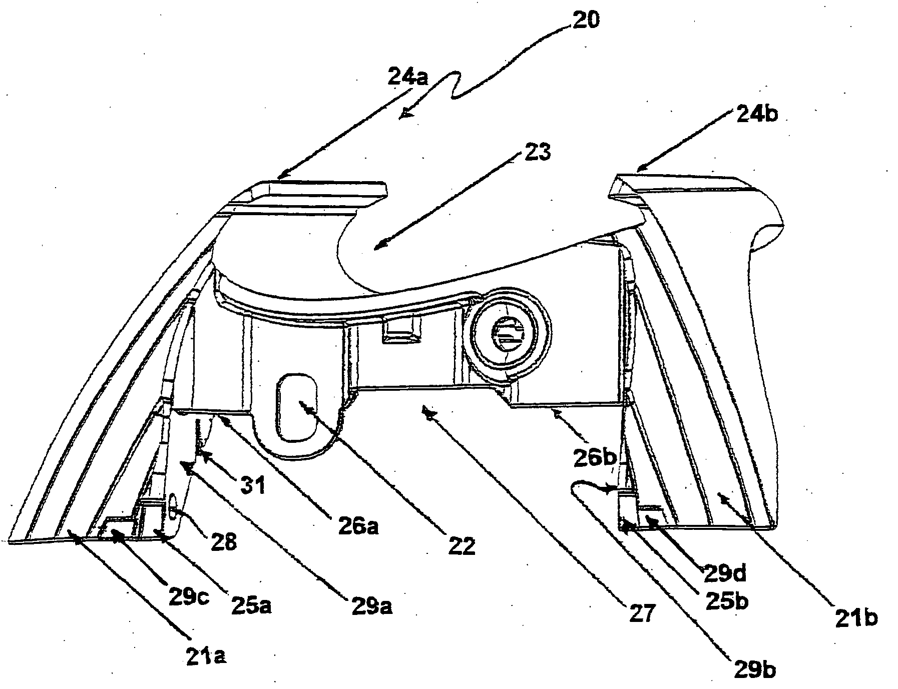
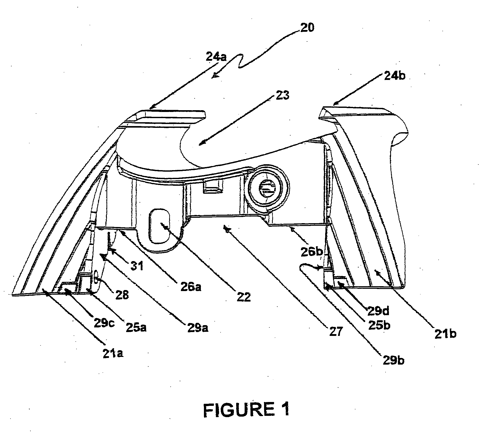
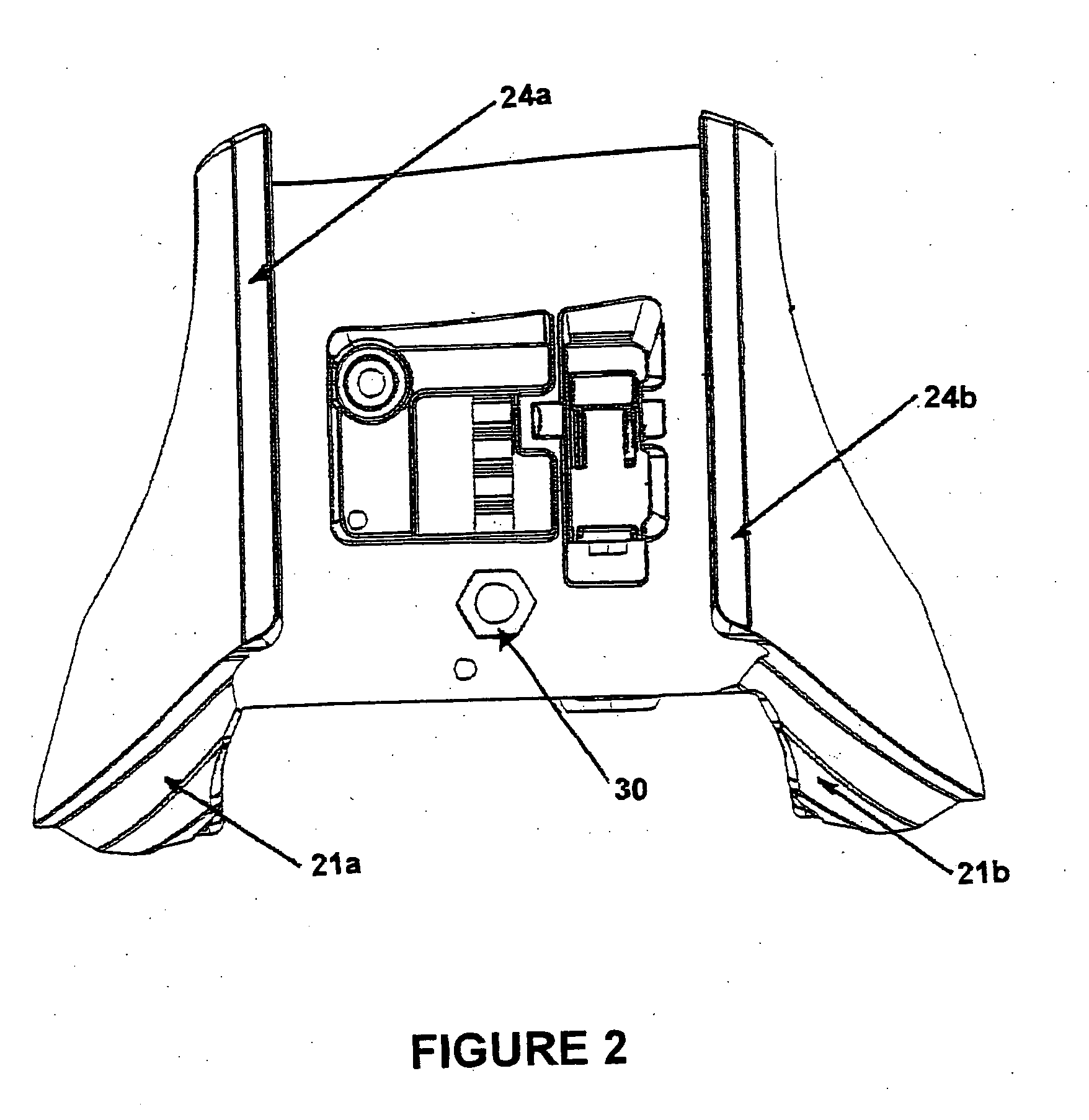
[0071]According to one embodiment of the invention, there is provided a leg 20 for a roof rack. The roof rack typically comprises a pair of legs at each end of a crossbar, the legs being used to support the crossbar and to directly or indirectly attach the roof rack to a vehicle. To attach the roof rack to a vehicle, the leg is adapted for coupling to a plurality of different mounting systems. Thus, separate mounting means may be used to attach the leg to the vehicle. Because the same leg can be used with a plurality of different mounts, a manufacturer and retailer can provide a lesser number of different components in a roof rack kit than in conventional roof rack kits. A standard kit comprising a crossbar and a pair of legs can be provided and separate kits for each mounting system can also be provided. Therefore, a consumer can purchase a standard kit together with whichever mounting system is required for the vehicle to which the roof rack will be attached.

[0072]FIG. 1 is a pers...


PUM


Abstract

The invention relates to a leg for a roof rack, the leg being adapted to be attachable to a plurality of different mounting systems by which to attach the leg to a vehicle. The invention also relates to different mounting systems for attaching to the leg for attaching the roof rack leg to a mount on the vehicle. In addition, the invention relates to a permanent pad mount for attaching to a vehicle and for use with the leg of the invention and, preferably, with one of the mounting systems of the invention to attach a roof rack to the vehicle.

Description

FIELD OF THE INVENTION[0001]The present invention relates to a versatile leg for a vehicle roof rack or load carrier and a roof rack comprising the same. The invention also relates to a novel pad mount and rail mount for attaching to a leg of a roof rack or load carrier.BACKGROUND OF THE INVENTION[0002]Roof racks are well known and are manufactured in a variety of configurations. Typically, roof racks include a crossbar with a leg at each end of the crossbar, the legs being used to support the crossbar and attach the crossbar to the roof of a vehicle. The legs are spaced apart from each other a selected distance. Generally, the distance between the legs is determined by the width of the vehicle to which the roof rack is mounted.[0003]The roof rack may be mounted to the vehicle using a variety of different mounting systems. Different types of vehicle typically have different roofs and require different mounts with which to attach a roof rack to the roof of the vehicle. For example, s...

Claims


Application Information

Patent Timeline
Patent Type & Authority Applications(United States)
IPC IPC(8): B60R9/04B60R11/00
CPCB60R9/058B60R9/04B60R9/045
Inventor HUBBARD, PETER DOUGLAS
Owner HUBCO AUTOMOTIVE
Why Eureka
Try Eureka