Surgical Instruments

A surgical, tubular shaft technology, applied in the fields of surgery, medical science, etc., can solve problems such as damage to nerve and vascular structures, achieve the effect of reducing the risk of tunnel misalignment and/or misalignment, and reducing inventory levels

Active Publication Date: 2019-07-26
SMITH & NEPHEW PLC
View PDF7 Cites 0 Cited by
  • Summary
  • Abstract
  • Description
  • Claims
  • Application Information

AI Technical Summary

Problems solved by technology

However, such surgical instruments tend to create tunnels that are not truly circular, or worse, can create tunnels along paths that diverge from the intended trajectory, and thus may not be anatomical and / or may cause damage to the nerve. damage to vascular structures

Method used


Image

  • Surgical Instruments
  • Surgical Instruments
  • Surgical Instruments

Examples


Embodiment Construction

[0028] U.S. Provisional Patent Application No. 61 / 733,479, filed December 5, 2012, entitled "SURGICAL INSTRUMENT," U.S. Provisional Patent Application No. 61 / 757,843, filed January 29, 2013, entitled "SURGICAL INSTRUMENT," and the 2013 The disclosure of US Provisional Patent Application No. 61 / 805,578, filed March 27, entitled "RETRO GUIDEWIRE REAMER," is hereby incorporated by reference in its entirety.

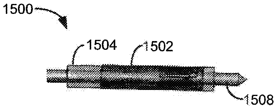
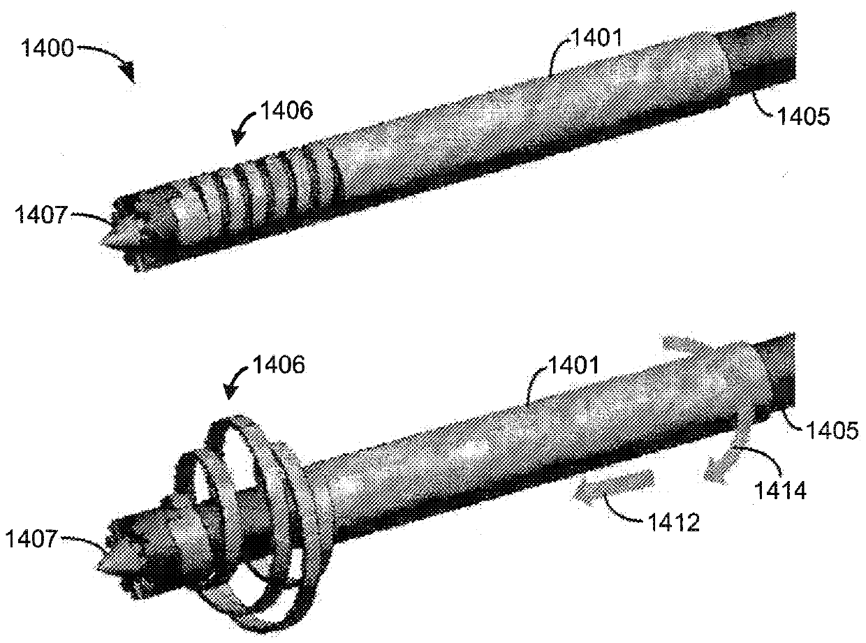
[0029] refer to figure 2 , discloses an illustrative embodiment of components of an exemplary surgical instrument 200 (also referred to herein as a "retrograde reamer") in accordance with the present application. like figure 2 As shown in , the components of the retrograde reamer 200 include an elongated inner shaft 206, an elongated outer tubular shaft 205, and a plurality of cutting members 204 movably coupled to the elongated outer tubular shaft 205. The outer tubular shaft 205 includes internal threads at its distal end 207 . The plurality of cutting members 204 (eg...


PUM


Abstract

A hollow retrograde reamer that is adjustable to produce tunnels of various diameters. The hollow retrograde reamer substantially reduces the risk of tunnel misposition and / or misalignment and can be adjusted to produce a range of tunnel diameters, allowing for reduced inventory levels for surgical cases.

Description

[0001] Cross References to Related Applications [0002] This application claims U.S. Provisional Patent Application No. 61 / 733,479, filed December 5, 2012, entitled "SURGICAL INSTRUMENT," and U.S. Provisional Patent Application No. 61 / 757,843, filed January 29, 2013, entitled "SURGICAL INSTRUMENT" and the benefit of priority to U.S. Provisional Patent Application No. 61 / 805,578, filed March 27, 2013, entitled "RETRO GUIDEWIRE REAMER." technical field [0003] The present invention relates generally to surgical instruments and, more particularly, to surgical instruments having at least one cutting member, such as a rotatable blade for use in retrograde cutting of bone. Background technique [0004] Some surgeons have used a retrograde approach to perform anterior cruciate ligament (ACL) surgery to create a femoral ACL tunnel (ie, "total internal ACL reconstruction"). like figure 1 As shown in , this approach typically entails surgery to drill the tunnel 102 in a retrograde...

Claims


Application Information

Patent Timeline
Patent Type & Authority Patents(China)
IPC IPC(8): A61B17/16
CPCA61B17/1617A61B17/1631A61B17/1633A61B17/1675A61B17/1697A61B17/1714A61B17/1764A61B2017/1602
Inventor S.M.鲍曼J.J.肯尼迪三世S.M.弗里克G.K.特雷纳J.B.泰勒D.J.卡拉汉B.J.布尔奎M.C.费拉加莫
Owner SMITH & NEPHEW PLC
Why Eureka
Try Eureka