Turbojet engine for aircraft, propulsion unit comprising such a turbojet engine and aircraft comprising such a propulsion unit

a technology for aircraft and propulsion units, which is applied in the direction of liquid fuel engines, machines/engines, and efficient propulsion technologies, etc., can solve the problem that no air stream can penetrate the cooling air

Inactive Publication Date: 2010-09-23
AIRBUS OPERATIONS (SAS)
View PDF11 Cites 0 Cited by
  • Summary
  • Abstract
  • Description
  • Claims
  • Application Information

AI Technical Summary

Problems solved by technology

Thus, no air stream can penetrate the cooling air lead-in conduit when the regulation device is closed.

Method used


Image

  • Turbojet engine for aircraft, propulsion unit comprising such a turbojet engine and aircraft comprising such a propulsion unit
  • Turbojet engine for aircraft, propulsion unit comprising such a turbojet engine and aircraft comprising such a propulsion unit
  • Turbojet engine for aircraft, propulsion unit comprising such a turbojet engine and aircraft comprising such a propulsion unit

Examples


Embodiment Construction

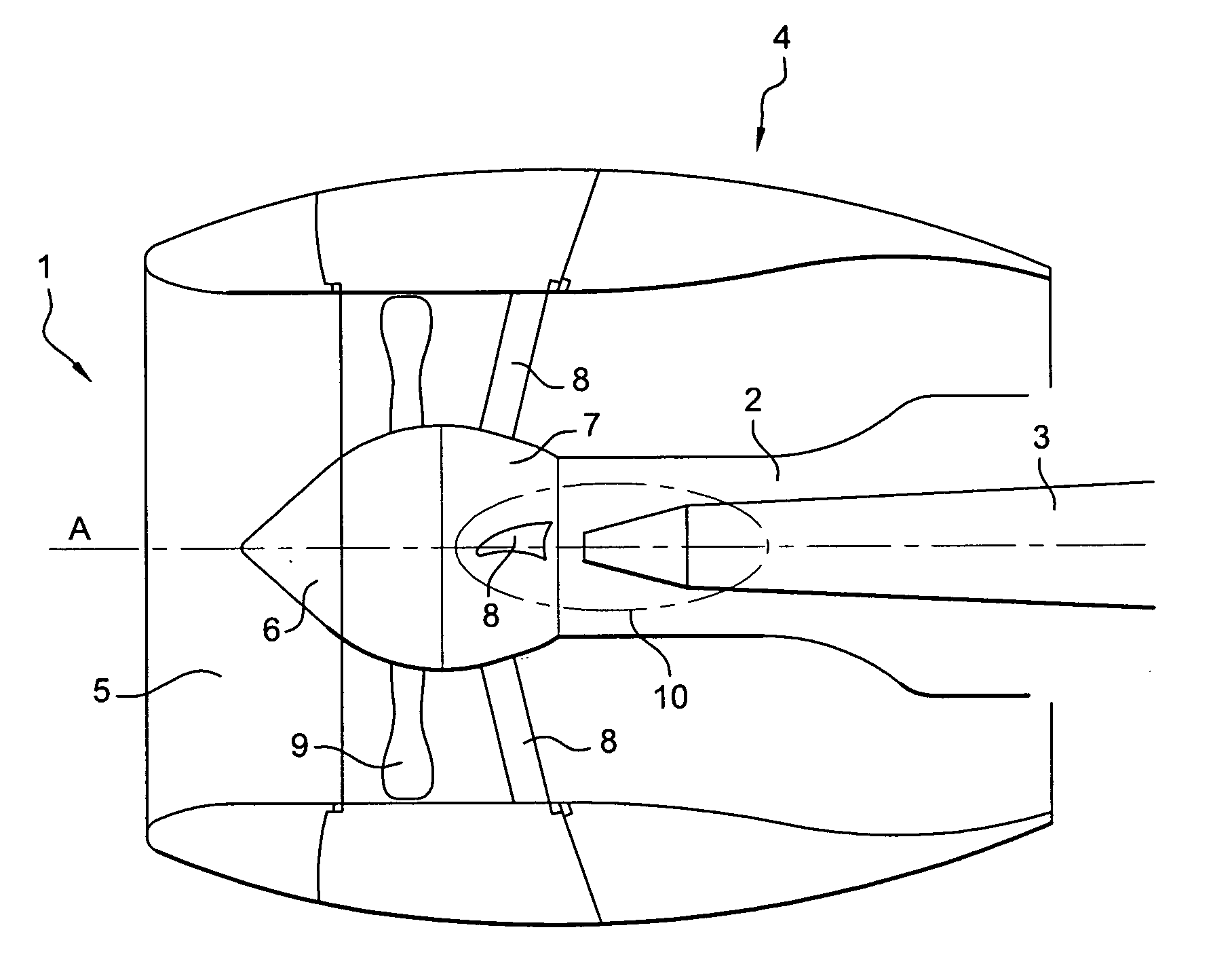
[0030]FIG. 1 shows a pod 1. The pod 1 has a turbojet engine housed in a hood 4. A fastening mast 3 joins the turbojet engine to the wing structure of an aircraft (not shown. The area in which the mast 3 is fastened to the turbojet engine 2 forms the bifurcation 10 separating the air stream into two secondary streams flowing respectively along the left flank and the right flank of the fastening mast 3. The bifurcation 10 is a fixed fairing that extends along the hood 4 and connects said hood 4 to the turbojet engine 2.

[0031]A front part 5 of the hood 4 forms an inlet by which air penetrates the turbojet engine to. A blower 6 bearing rotating blades 9 transmits pressure to the air stream which has to go through the pod 1. A fixed rear end 7 of the blower 6 carries static blades 8 whose function is to rectify the air stream in order to give it a single direction, parallel to the axis A of the turbojet engine 1. Only three static, guiding blades 8 are shown in FIG. 1. The static guiding...


PUM


Abstract

A propulsion unit comprises a turbojet engine and a thermal exchanger, situated above the turbojet engine. The turbojet engine comprises a regulation device to regulate an air flow-rate in a cooling air lead-in conduit conveying a stream of cooling air into a thermal exchanger, The regulation device regulates the air flow-rate upstream with respect to the cooling air lead-in conduit

Description

RELATED APPLICATION[0001]This application claims priority to French Application No. FR 05 52343 filed Jul. 28, 2005.BACKGROUND OF THE INVENTION[0002]1. Field of the Invention[0003]The invention relates to a turbojet engine for aircraft. More specifically, the invention relates to a regulation device used to regulate a flow-rate of cooling air in a thermal exchanger situated above the turbojet engine.[0004]2. Background of the Invention[0005]There are known ways of supplying an air-conditioning circuit in an aircraft pressurized cabin with a stream of compressed hot air tapped at the compressor of a turbojet engine. This stream of hot air is at least partially cooled by means of a cooling air stream tapped from the blower channel of the turbojet engine before it is injected into the air-conditioning circuit. The thermal exchange between the stream of hot air to be cooled and the stream of cooling air takes place in a thermal exchanger. The thermal exchanger comprises a case, generall...

Claims


Application Information

Patent Timeline
Patent Type & Authority Applications(United States)
IPC IPC(8): B64D33/02F02K99/00F04D29/56
CPCF01D9/065F02C6/08Y02T50/675F02K3/06F02C7/185Y02T50/60Y10T137/0645
Inventor MARCHE, HERVE
Owner AIRBUS OPERATIONS (SAS)
Why Eureka
Try Eureka