Method of Automatically Programming a Load Control Device Using a Remote Identification Tag

a remote identification and load control technology, applied in the field of load control systems, can solve the problems of tedious prior art reconfiguration methods and even more tedious prior art methods

Active Publication Date: 2010-09-23
LUTRON TECH CO LLC
View PDF57 Cites 70 Cited by
  • Summary
  • Abstract
  • Description
  • Claims
  • Application Information

AI Technical Summary

Benefits of technology

[0011]According to the present invention, a method of automatically programming a new load control device that replaces an old load control device of a load control system takes advantage of a remote identification tag located in the vicinity of the old load control device. The remote identification tag stores an identifier that is representative of a location in which the old load control device is installed. The method comprises the steps of: (1) storing a setting of an old load control device in a memory of a controll...

Problems solved by technology

The prior art method of reconfiguration can be tedious as the user must input the serial numbers of both the failed and new ballasts.
If many...

Method used


Image

  • Method of Automatically Programming a Load Control Device Using a Remote Identification Tag
  • Method of Automatically Programming a Load Control Device Using a Remote Identification Tag
  • Method of Automatically Programming a Load Control Device Using a Remote Identification Tag

Examples


Embodiment Construction

[0023]The foregoing summary, as well as the following detailed description of the preferred embodiments, is better understood when read in conjunction with the appended drawings. For the purposes of illustrating the invention, there is shown in the drawings an embodiment that is presently preferred, in which like numerals represent similar parts throughout the several views of the drawings, it being understood, however, that the invention is not limited to the specific methods and instrumentalities disclosed.

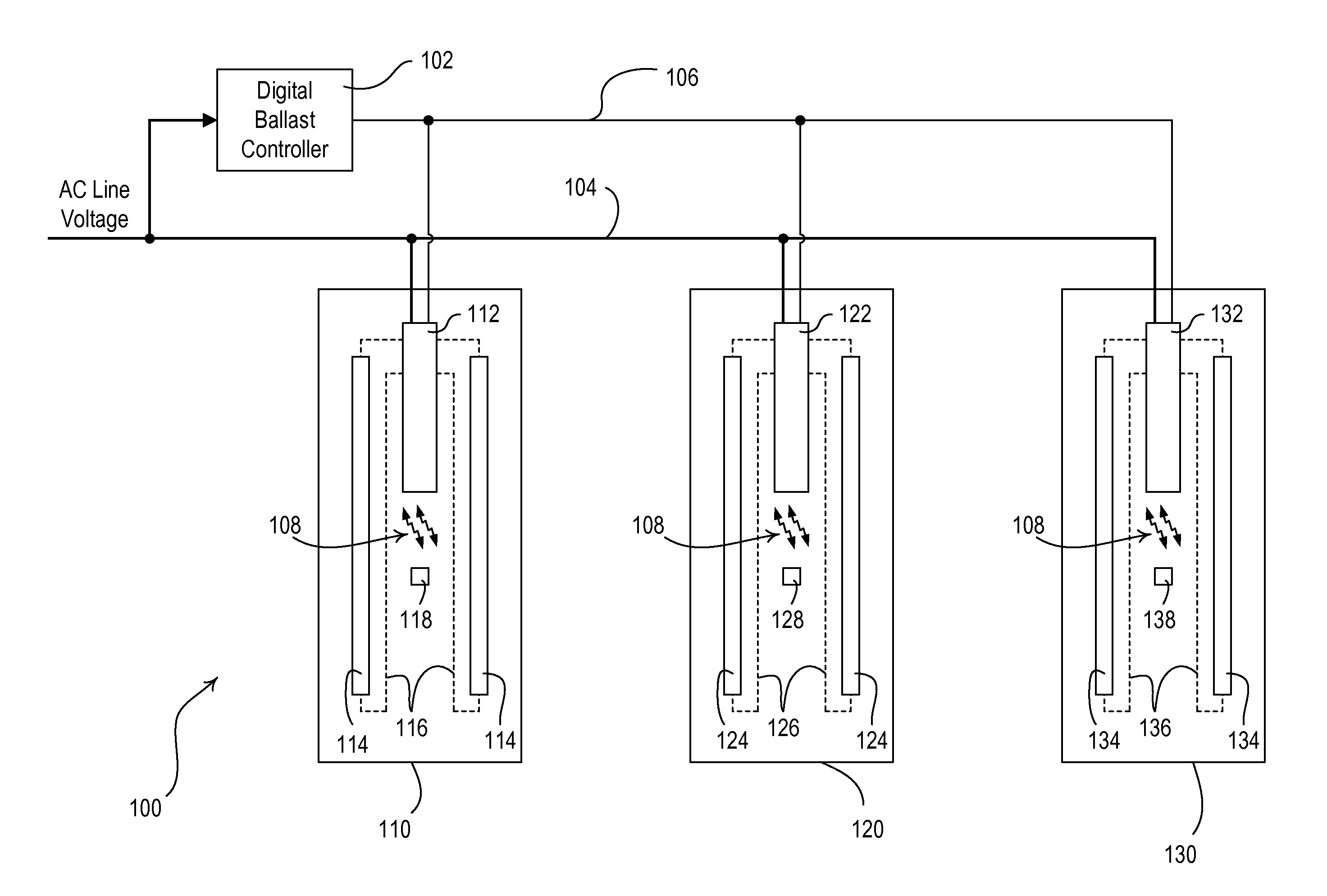
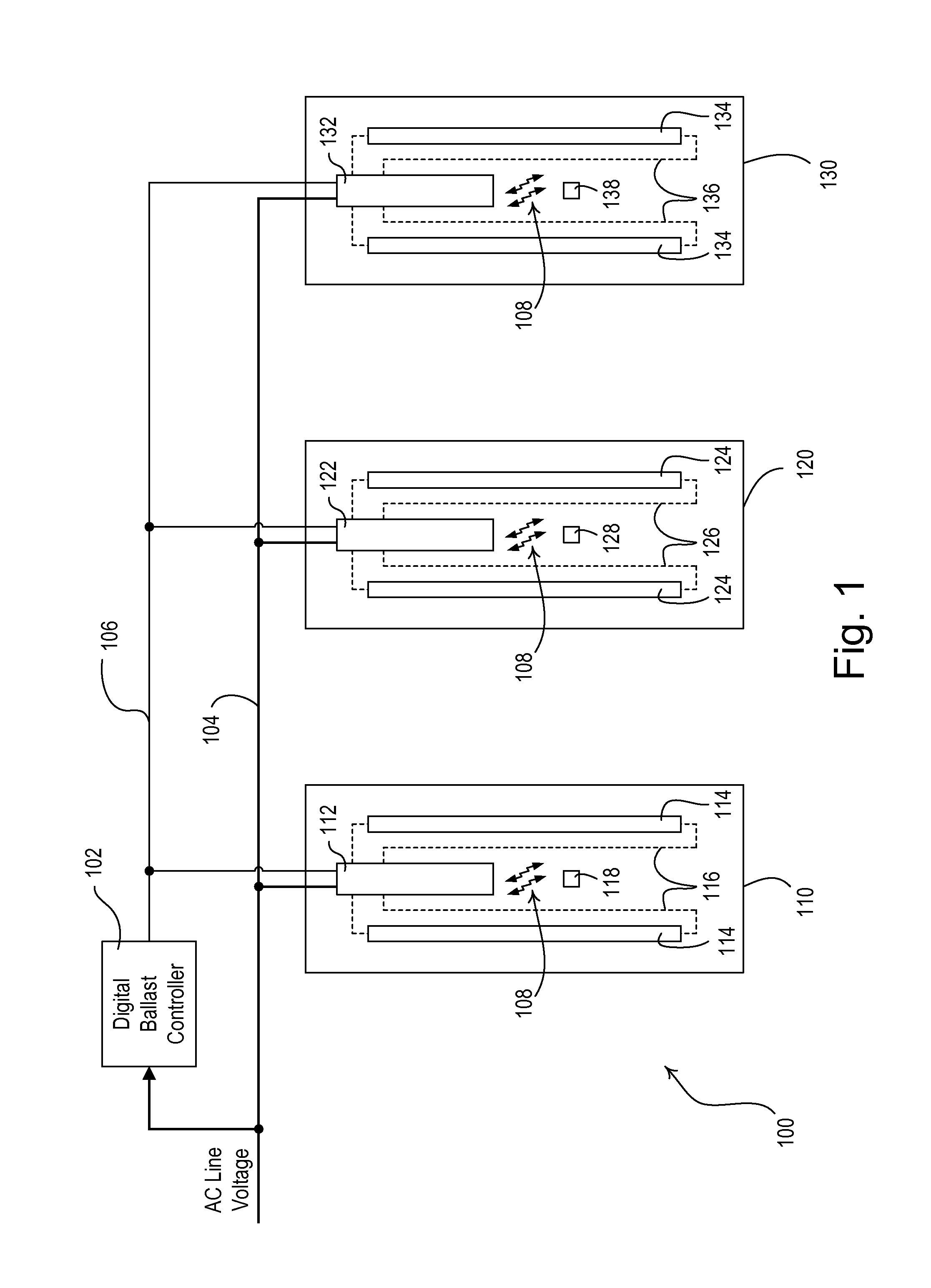
[0024]FIG. 1 is a simplified block diagram of a fluorescent lighting control system 100 for control of the intensities of a plurality of fluorescent lamps 114, 124, 134 according to a first embodiment of the present invention. The fluorescent lighting control system 100 includes a plurality of lighting fixtures 110, 120, 130 (e.g., three fixtures) in which the lamps 114, 124, 134 are located. Each fixture 110, 120, 130 also includes a respective digital electronic dimming ballas...


PUM


Abstract

A method of automatically programming a new load control device that replaces an old load control device takes advantage of a remote identification tag (e.g., an RFID tag) located in the vicinity of the old device. The remote identification tag stores an identifier that is representative of a location in which the old device is installed. The method includes the steps of: (1) storing a setting of an old device in a memory of a controller; (2) associating the setting with the identifier of the old device in the memory of the controller; (3) the new device retrieving the identifier from the remote identification tag after the new device is installed in the location of the old device; (4) the new device transmitting the identifier to the controller; and (5) the controller transmitting the setting of the old device to the new device in response to receiving the identifier.

Description

CROSS-REFERENCE TO RELATED APPLICATIONS[0001]This application is a non-provisional application of commonly-assigned U.S. Provisional Application Ser. No. 61 / 162,018, filed Mar. 20, 2009, entitled METHOD OF AUTOMATICALLY PROGRAMMING A LOAD CONTROL DEVICE USING A REMOTE IDENTIFICATION TAG, the entire disclosure of which is hereby incorporated by reference.BACKGROUND OF THE INVENTION[0002]1. Field of the Invention[0003]The present invention relates to load control systems for controlling the amount of power delivered to one or more electrical loads and, specifically, to a method of automatically programming a new load control device, such as an electronic dimming ballast, using a remote identification tag, such as a radio-frequency identification (RFID) transponder that is associated with the location (e.g., fixture) in which the new load control device is installed.[0004]2. Description of the Related Art[0005]A typical prior art load control system is operable to control the amount of...

Claims


Application Information

Patent Timeline
IPC IPC(8): H04Q5/22G05B11/01H05B44/00
CPCH05B37/0254H05B37/0272H05B37/0263H05B37/02G06K7/10297H05B47/18H05B47/10H05B45/10H05B47/185
Inventor VESKOVIC, DRAGAN
Owner LUTRON TECH CO LLC
Why Eureka
Try Eureka