
Automatic Programming method and device

a programming method and programming device technology, applied in the field of automatic programming methods and devices, can solve problems such as deteriorating working efficiency

Active Publication Date: 2007-02-01
MITSUBISHI ELECTRIC CORP
View PDF8 Cites 25 Cited by
  • Summary
  • Abstract
  • Description
  • Claims
  • Application Information

AI Technical Summary

Benefits of technology

The present invention provides an automatic programming method for selecting workpiece data from a database, creating a workpiece model for lathe turning based on the selected data, and creating a program for controlling a numerical control device based on the workpiece model and the product model. The method allows for the selection of minimum workpiece data involving the product shape and having the smallest diameter for lathe turning around the turning axis, resulting in optimum workpiece data. This results in improved efficiency and accuracy in the programming process for lathe turning.

Problems solved by technology

H10-207523, however, since the operator selects the workpiece from the workpiece-shape data, long time is required for selecting the work, thereby deteriorating the working efficiency.

Method used


Image

  • Automatic Programming method and device
  • Automatic Programming method and device
  • Automatic Programming method and device

Examples


first embodiment

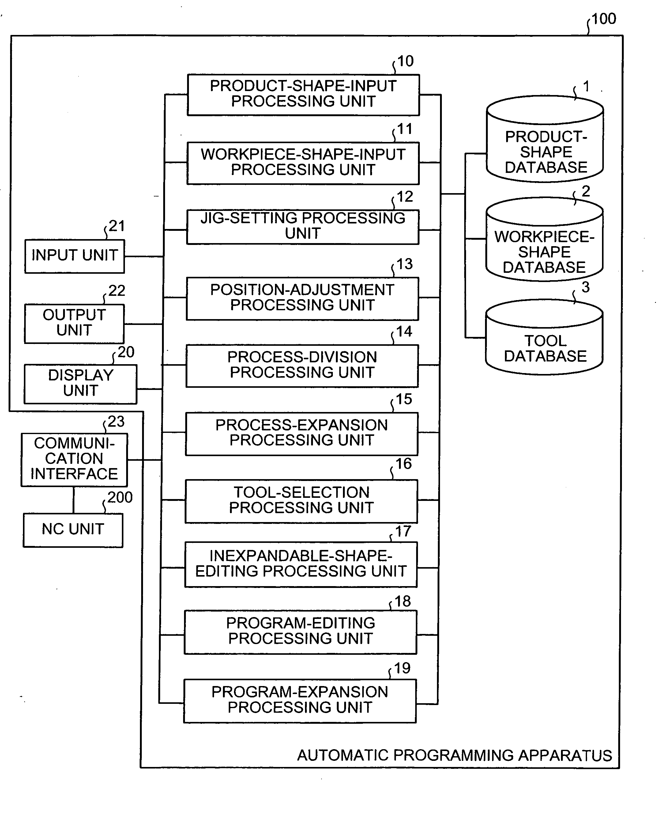
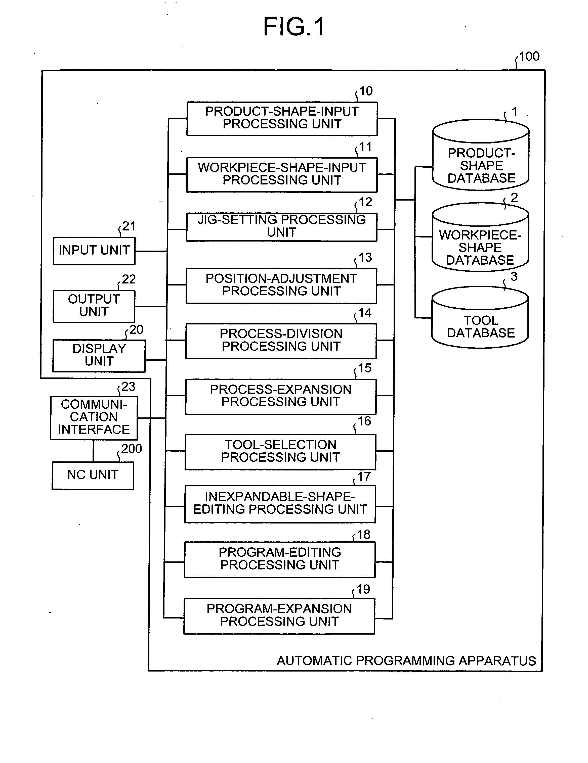
[0070]FIG. 1 is a block diagram of a configuration of an automatic programming apparatus according to the present invention. An automatic programming apparatus 100 includes, as a basic component, NC creating software for directly fetching data relating to a product shape and a workpiece-shape from CAD data, and creating an NC creation program for machining a product from a material (workpiece) in an interactive mode with an operator, by various data such as the fetched product shape data and workpiece-shape data. The automatic programming apparatus is installed in a computer such as a microcomputer. The NC creation program is described in a predetermined language higher than the NC program.

[0071] The automatic programming apparatus 100 can be applied to a two-spindle machine tool having two spindles, that is, a main spindle and a sub-spindle, and a one-spindle machine tool having only the main spindle. However, the automatic programming apparatus applied to the two-spindle machine t...

second embodiment

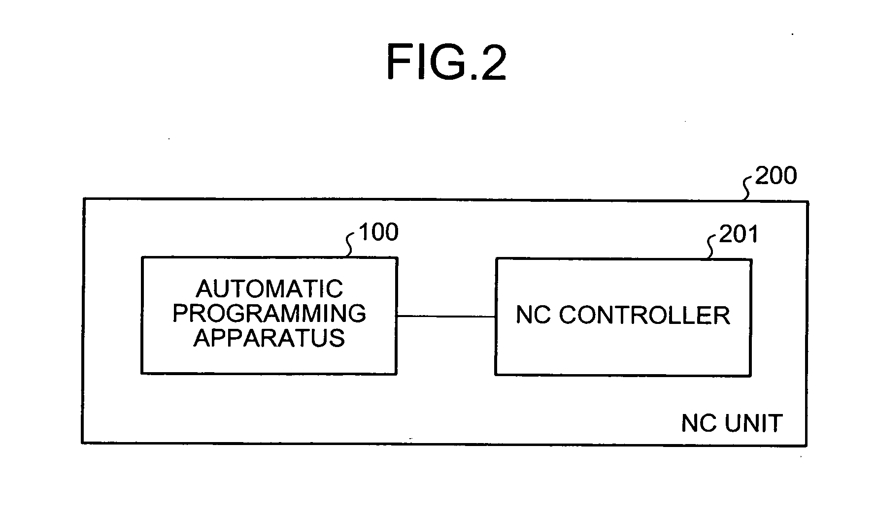
[0244] the present invention will be explained with reference to FIGS. 56 and 57. The automatic programming apparatus in the first embodiment is an automatic programming apparatus applied to the two-spindle machine tool having two spindles, that is, the main spindle and the sub-spindle installed so as to face the main spindle. However, the automatic programming apparatus in the second embodiment is an automatic programming apparatus applicable to the two-spindle machine tool having the two spindles of the main spindle and the sub-spindle, and a one-spindle machine tool having only the main spindle.

[0245] In the case of the two-spindle machine tool, machining in the first process and machining in the second process can be performed continuously by the main spindle side and the sub-spindle side. Therefore, in the automatic programming apparatus, one program for continuously executing the machining in the first process and the machining in the second process is created. In contrast, in...


PUM


Abstract

Workpiece data involving a product shape and having a smallest diameter for lathe turning around a turning axis is selected from the workpiece database, by comparing dimension data of a workpiece model with dimension data of a product model in a state in which the product model is arranged on the turning axis and the workpiece model is arranged so that a center axis of each workpiece matches a center of the turning axis. The workpiece model for lathe turning is created based on the selected workpiece data.

Description

TECHNICAL FIELD [0001] The present invention relates to a technology for creating a numerical control (NC) program using computer-aided-design (CAD) data, such as a product shape and a workpiece shape, with an automatic selection of an optimum workpiece corresponding to a product. BACKGROUND ART [0002] In a machine tool on which an NC unit (numerical control unit) is mounted, a workpiece is machined into a desired product shape by executing the NC program. To create the NC creation program for creating the NC machining program, recently, an automatic programming technique using a microcomputer referred to as an automatic programming apparatus has been frequently used. [0003] The primitive automatic programming apparatuses were not connected to the CAD data, and hence, it was necessary to perform programming, while watching the machining shape in a drawing or the like. However, recently, some techniques relating to the automatic programming apparatus that creates the NC machining pro...

Claims


Application Information

Patent Timeline
Patent Type & Authority Applications(United States)
IPC IPC(8): G06F19/00G05B19/4097B23Q15/00G05B19/409G05B19/4093G05B19/4155
CPCG05B19/4093G05B2219/36304G05B2219/35576G05B2219/35259Y02P90/02G06F9/06G05B19/409B23Q15/00Y10S715/964
Inventor KAMIYA, TAKASHIKATANO, HIROSHIIRIGUCHI, KENJIMATSUBARA, SUSUMU
Owner MITSUBISHI ELECTRIC CORP
Learn More