Solid-state laser device and image display device

a laser device and laser technology, applied in the direction of optical elements, planar/plate-like light guides, instruments, etc., can solve the problems of unstable output, difficult to obtain a high output, unstable harmonic output, etc., and achieve the effect of not increasing the number of parts

Active Publication Date: 2010-09-23
PANASONIC CORP
View PDF11 Cites 14 Cited by
  • Summary
  • Abstract
  • Description
  • Claims
  • Application Information

AI Technical Summary

Benefits of technology

[0017]In order to solve the above problems, an object of the present invention is to provide a solid-state laser device and an image display device capable of stabilizing a harmonic output and using a plurality of harmonics without increasing the number of parts.

Problems solved by technology

In the internal resonator type semiconductor laser excited solid-state laser device shown in FIG. 18, an output may become unstable due to the re-incidence of harmonics on the wavelength conversion element.
Since the harmonic is reversely converted into the fundamental wave in the optical resonator in this way, the reversely converted fundamental wave and the original fundamental wave interfere to make the harmonic output unstable.
However, since one harmonic is absorbed in the example of patent literature 1, the harmonic output becomes about half, wherefore efficiency is poor and it is difficult to obtain a high output.
Thus, the direction of either one of the beams needs to be changed if it is tried to use both of the two output harmonics, which leads to an increase in optical parts and a cost increase.

Method used


Image

  • Solid-state laser device and image display device
  • Solid-state laser device and image display device
  • Solid-state laser device and image display device

Examples


first embodiment

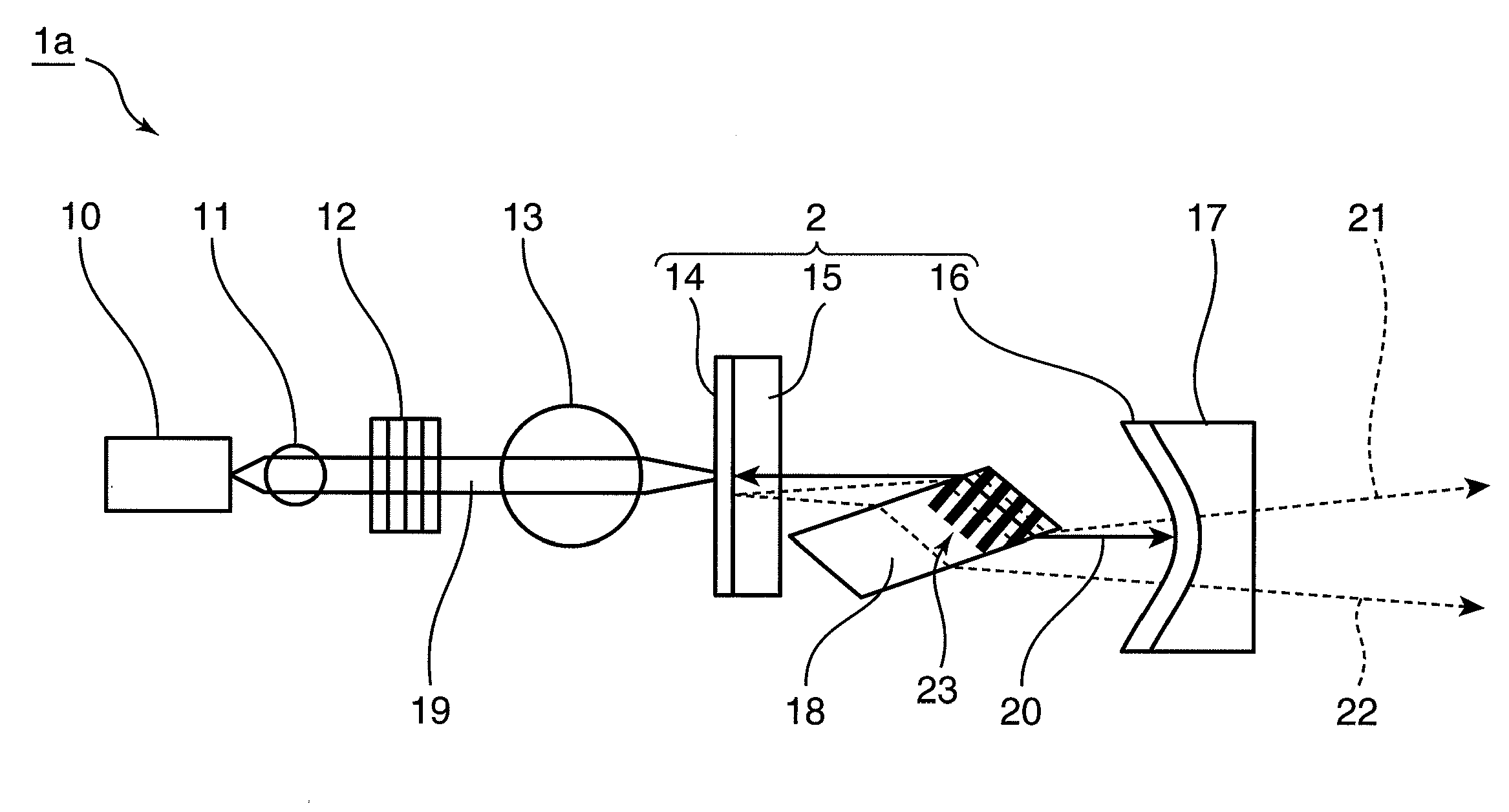
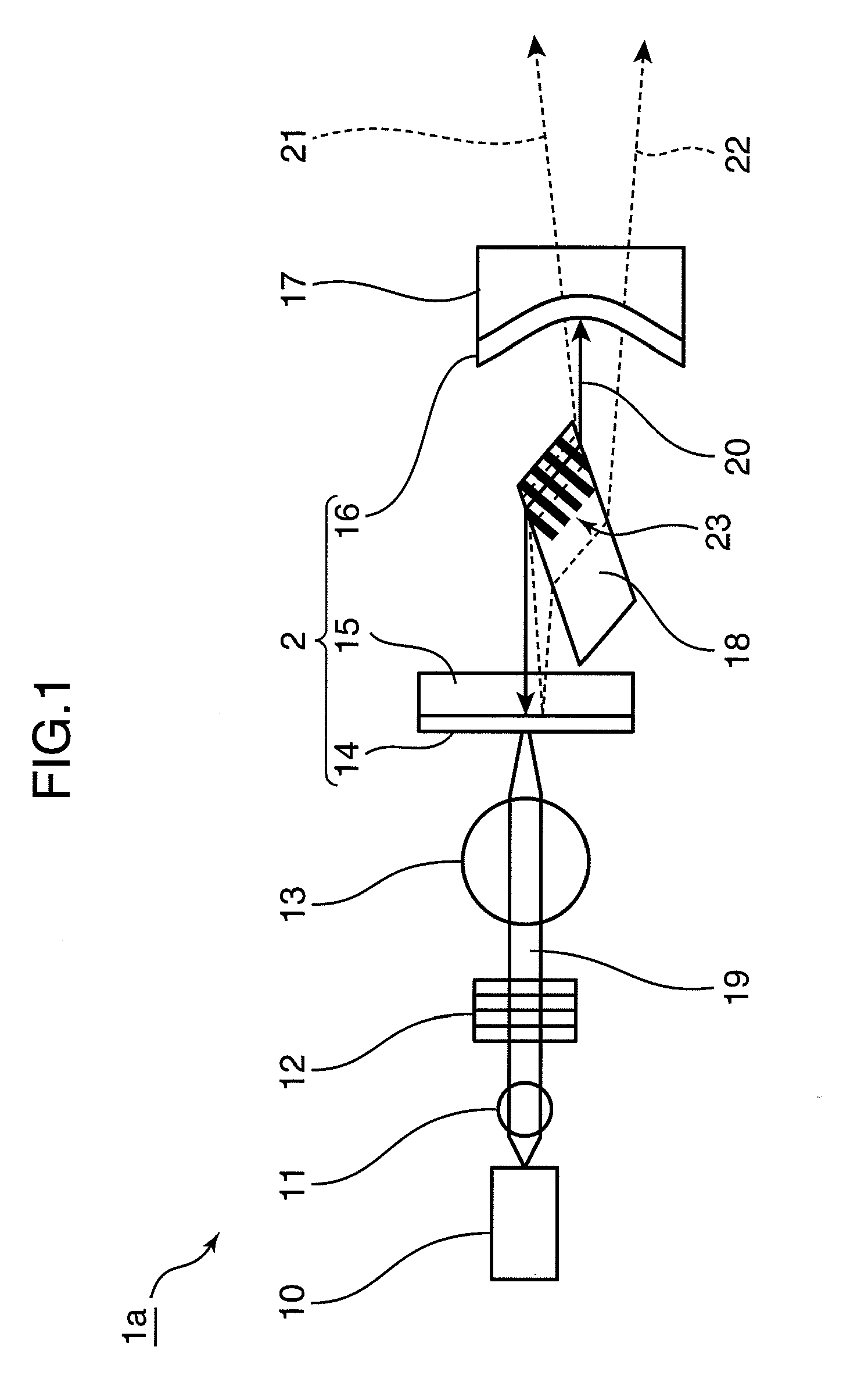
[0044]FIG. 1 is a diagram showing the construction of an internal resonator type solid-state laser device 1a according to a first embodiment of the present invention. The solid-state laser device 1a of the first embodiment is provided with a semiconductor laser light source 10, a rod lens 11, a volume Bragg grating (hereinafter, referred to as VBG) 12, a ball lens 13, an optical resonator 2, a concave mirror 17 and a wavelength conversion element 18.

[0045]The semiconductor laser light source 10 emits a laser beam for pumping (hereinafter, referred to as pump beam) 19. The optical resonator 2 is comprised of a solid laser crystal 15 to be excited by the incidence of the pump beam 19 to oscillate a fundamental wave 20 and a pair of fundamental wave reflective coats 14, 16 arranged at the opposite sides of the solid laser crystal 15. The wavelength conversion element 18 is arranged in the optical resonator 2 for converting the fundamental wave 20 into a plurality of harmonics 21, 22.

[0...

second embodiment

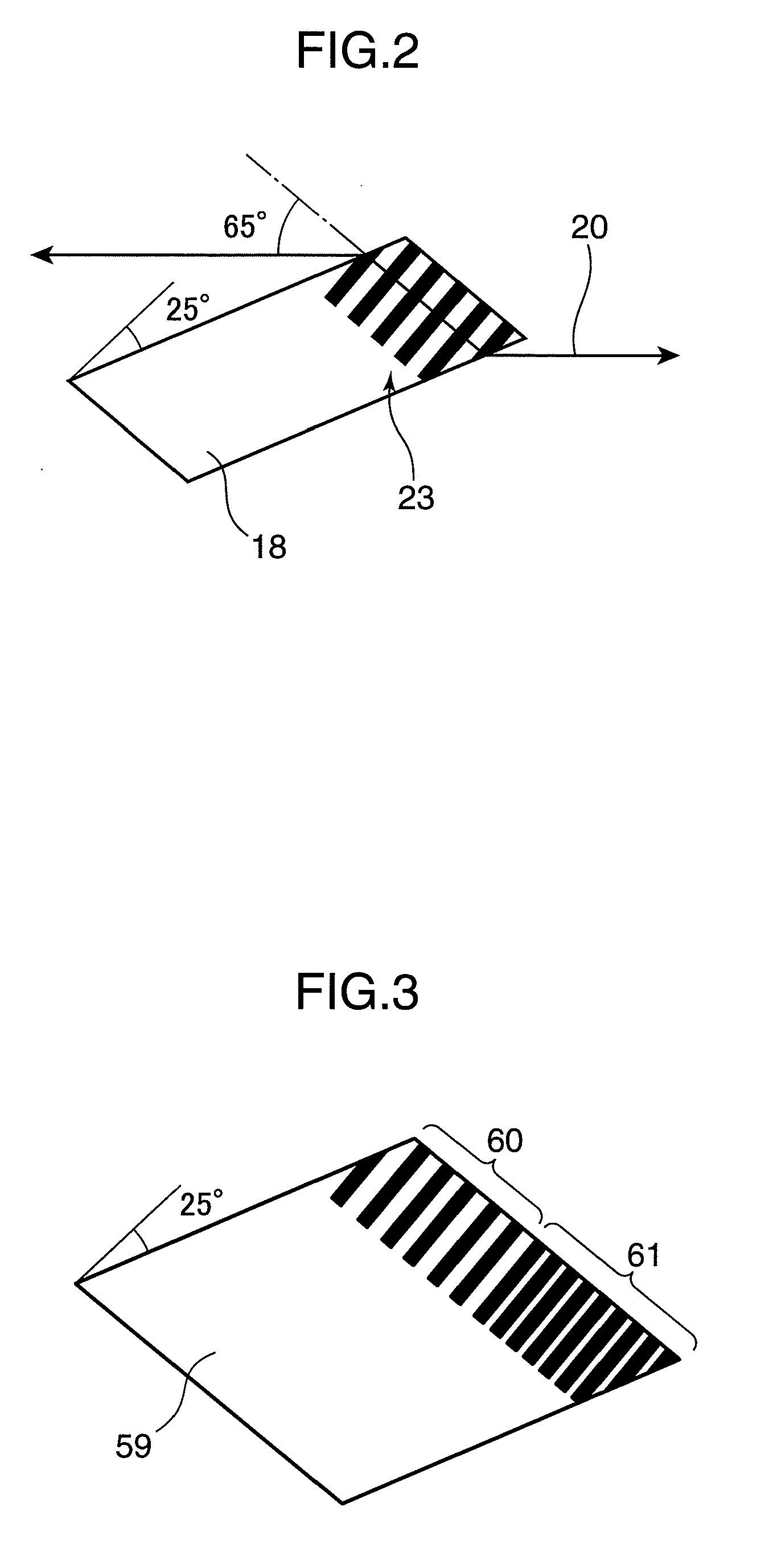
[0067]In a second embodiment is described an example in which a wavelength conversion element formed with a plurality of polarization reversal regions with different periods is used by being inserted into an optical resonator. The wavelength conversion element used in the second embodiment is obliquely ground and inserted at a Brewster angle into the optical resonator similar to the first embodiment.

[0068]FIG. 3 is a diagram showing the construction of a wavelength conversion element 59 used in a solid-state laser device according to the second embodiment of the present invention. In the second embodiment, the construction other than the wavelength conversion element 59 is the same as the solid-state laser device of the first embodiment. As shown in FIG. 3, the wavelength conversion element 59 is formed with a first polarization reversal region 60 and a second polarization reversal region 61 with a period different from that of the first polarization reversal region 60.

[0069]FIG. 4 ...

third embodiment

[0077]In a third embodiment is described an example in which a plurality of obliquely ground wavelength conversion elements are inserted at a Brewster angle into an optical resonator.

[0078]FIG. 5 is a diagram showing the construction of a solid-state laser device according to the third embodiment of the present invention. A solid-state laser device 1b shown in FIG. 5 is provided with a semiconductor laser light source 10, a rod lens 11, a VBG 12, a ball lens 13, an optical resonator 2, a concave mirror 17 and wavelength conversion elements 18, 24. A basic construction of the solid-state laser device 1b of the third embodiment is similar to that of the solid-state laser device 1a of the first embodiment, but the wavelength conversion element 24 is inserted in the optical resonator 2.

[0079]As shown in FIG. 5, the number of harmonics to be output increases by adding the wavelength conversion element 24 between the wavelength conversion element 18 and a fundamental wave reflective coat ...


PUM


Abstract

A semiconductor laser light source 10 emits a laser beam for pumping. An optical resonator 2 includes a solid laser crystal 15 to be excited by the incident of a laser beam to oscillate a fundamental wave 20 and a pair of fundamental wave reflective coats 14, 16 arranged at the opposite sides of the solid laser crystal 15. A wavelength conversion element 18 converts the fundamental wave 20 into a plurality of harmonics 21, 22. The wavelength conversion element 18 is so arranged in the optical resonator 2 that the optical axis of at least one of the plurality of harmonics 21, 22 generated in the optical resonator 2 is made different from that of the fundamental wave 20 and the at least one harmonic 22 whose optical axis is made different is output substantially in the same direction as the other harmonic 21. By this construction, it is possible to stabilize a harmonic output and utilize a plurality of harmonics without increasing the number of parts.

Description

FIELD OF THE INVENTION[0001]The present invention relates to an internal resonator type solid-state laser device using a solid laser crystal and a wavelength conversion element, and an image display device using the solid-state laser device.BACKGROUND TECHNOLOGY[0002]A solid-state laser device excited by a semiconductor laser is for causing laser oscillation by exciting a solid laser crystal by a laser beam from a semiconductor laser light source, has characteristics of having a small size, a light weight, a long life, and a high electrical / optical conversion efficiency, a stable operation and the like and is used in various industrial fields.[0003]FIG. 18 is a diagram showing the construction of a conventional internal resonator type solid-state laser device 101 excited by a semiconductor laser. A pump beam 119 having a wavelength of about 808 nm and emitted form a semiconductor laser light source 110 passes through a wavelength locking device 112 and is incident on a solid laser c...

Claims


Application Information

Patent Timeline
Patent Type & Authority Applications(United States)
IPC IPC(8): H01S3/109
CPCG02B6/0026H04N9/3197G02B6/003G02B6/0066G02B6/0068G02B6/0076G02F1/133621H01S3/0619H01S3/08059H01S3/08086H01S3/09415H01S3/101H01S3/109H04N9/3158H04N9/3161G02B6/0028
Inventor YOKOYAMA, TOSHIFUMIMIZUUCHI, KIMINORIMIZUSHIMA, TETSUROITOH, TATSUO
Owner PANASONIC CORP
Why Eureka
Try Eureka