Thermal overload relay

a relay and overload technology, applied in relays, protective switch details, protective switch terminals/connections, etc., can solve the problems of increasing the heating amount of the heating element containing the space for the s-phase, and affecting the electrical connection. the effect of easy recognition

a relay and overload technology, applied in relays, protective switch details, protective switch terminals/connections, etc., can solve the problems of increasing the heating amount of the heating element containing the space for the s-phase, and affecting the electrical connection. the effect of easy recognition

US20100245021A1Inactive Publication Date: 2010-09-30FUJI ELECTRIC FA COMPONENTS & SYST CO LTD

Image

  • Thermal overload relay
  • Thermal overload relay
  • Thermal overload relay

Examples


Embodiment Construction

[0037]In the following, an embodiment for carrying out the invention (hereinafter referred to as an embodiment) will be explained in detail with reference to the attached drawings.

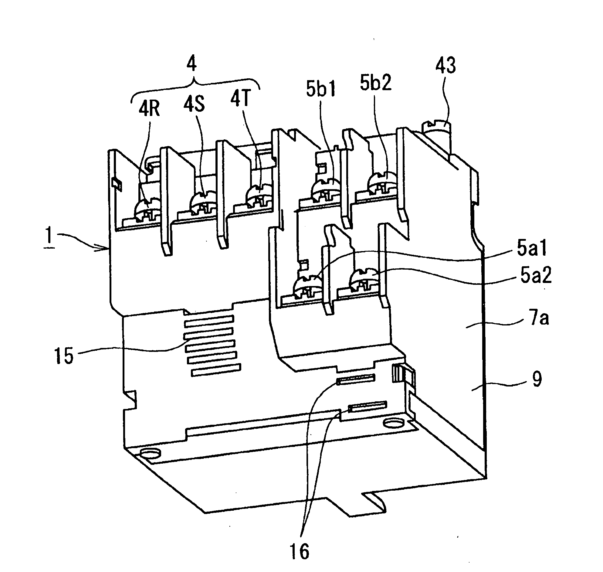
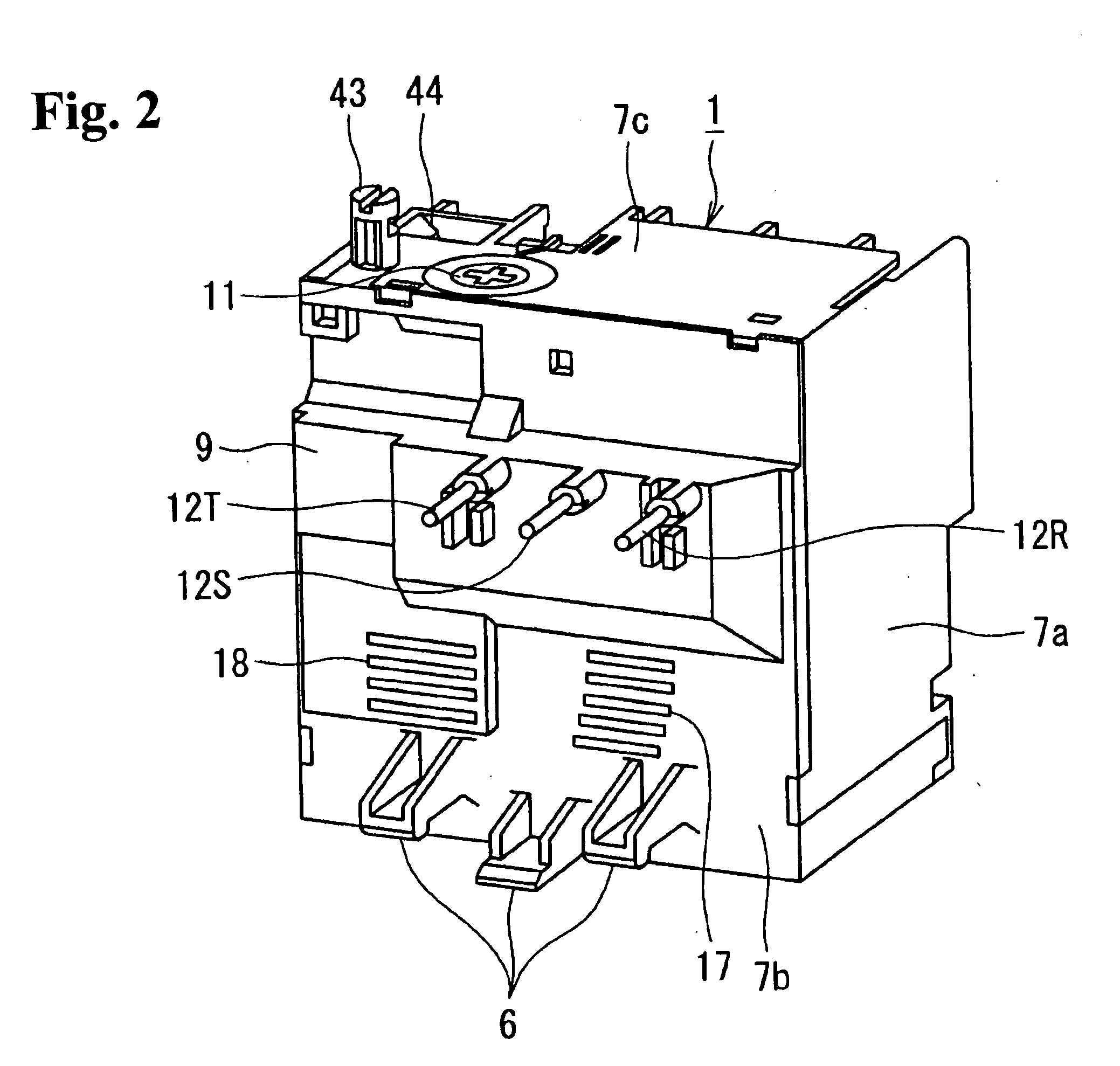
[0038]FIG. 1 is a perspective view showing an external appearance of the thermal overload relay according to an embodiment of the invention as seen from the side provided with load side main circuit terminals and auxiliary circuit terminals, FIG. 2 is a perspective view showing an external appearance of the thermal overload relay according the embodiment of the invention as seen from the side with connecting wires connected to an electromagnetic contactor and FIG. 3 is a top view showing the thermal overload relay according to the embodiment of the invention.

[0039]As shown in FIG. 1 to FIG. 3, a thermal overload relay 1 is provided with a casing 9 including a cubic insulation case 7a, a side cover 7b attached to an opening opened on the side of the insulation case 7a and an upper face cover 7c of the insul...


PUM


Abstract

A thermal overload relay has an actuator mechanism that generates an operating force by bending of a main bimetal with a heating wire wound thereon; a switching mechanism that is driven by the operating force from the actuator mechanism; a contact changeover mechanism wherein contacts are changed by the switching mechanism operation; and a casing that contains the actuator, the switching and the contact changeover mechanisms. The casing has main circuit terminals and auxiliary circuit terminals arranged on one side, the main circuit terminals electrically connecting the thermal overload relay to an electric load device, and the auxiliary circuit terminals electrically connecting the thermal overload relay to another electric device. When the casing is viewed in plan, the main circuit terminals are aligned and, the auxiliary circuit terminals are arranged in a position offset from the position of the alignment of the main circuit terminals.

Description

BACKGROUND OF THE INVENTION AND RELATED ART STATEMENT[0001]The present invention relates to a thermal overload relay carrying out switching of contacts when an overcurrent is detected and particularly to an improvement of a casing of a thermal overload relay containing an actuator mechanism, a switching mechanism and a contact changeover mechanism.[0002]A thermal overload relay has a casing containing therein an actuator mechanism provided with bimetals each having a heating wire (heater) wound thereon, a shifter engaged with each of the open ends of the bimetals to be supported movably in the horizontal direction, a switching mechanism linked with a shifter to be operated by the shift of the shifter and a contact changeover mechanism carrying out changeover of contacts by the operation of the switching mechanism (see JP-A-2004-172122, for example).[0003]Such a thermal overload relay is an electric device that is connected with an electromagnetic contactor to thereby form an electro...

Claims


Application Information

Patent Timeline
30 Sep 2010
Publication
US20100245021A1
IPC
H01H71/16
CPC
H01H83/223; H01H71/08
Inventors
FURUHATA, YUKINARI; MORISHITA, FUMIHIRO