[0020]An
input device according to the present invention includes: a disk-shaped key whose four positions of the top, bottom, right and left become push-buttons; metal domes which are arranged at the positions corresponding to four positions of the top, bottom, right and left of the disk-shaped key and are brought into a conducting state when the disk-shaped key is pressed down; a touch sensor which is arranged over the respective metal domes corresponding to four positions of the top, bottom, right and left of the disk-shaped key, and in which an electrical value changes in response to changes of the point on which pressure is applied; and a convex portion for a touch sensor which is provided on the reverse side of the disk-shaped key and applies pressure on the touch sensor when a finger touches the disk-shaped key. Consequently, the disk-shaped key is capable of acting as both a four-direction key and a touch key with which an input operation is performed by shifting the finger in a
circular motion. As the touch sensor is arranged over the metal domes, it is possible to enlarge an area of the disk-shaped key. And, when the disk-shaped key is used as the touch key, a simple operation to slide the finger in a continuous
circular motion is necessary without releasing the finger from the key. Therefore, a favorable
operability can be achieved. Further, as the disk-shaped key acts as both the four-direction key and the touch key, there is no need to provide the four-direction key and the touch key separately, which prevents an erroneous operation or a malfunction caused by touching a plurality of keys at the same time with the finger. In the result, a favorable
operability can be achieved. Further, as the touch sensor includes a metal plate, it is capable of improving the reliability for shock or
pressure resistance when the disk-shaped key is operated. Moreover, it is possible to prevent the entire touch sensor from bending, to give a user a favorable operational feeling, and to improve operation accuracy.DESCRIPTION OF EXEMPLARY EMBODIMENTS
[0021]Hereinafter, exemplary embodiments of the invention will be explained with reference to the drawings.
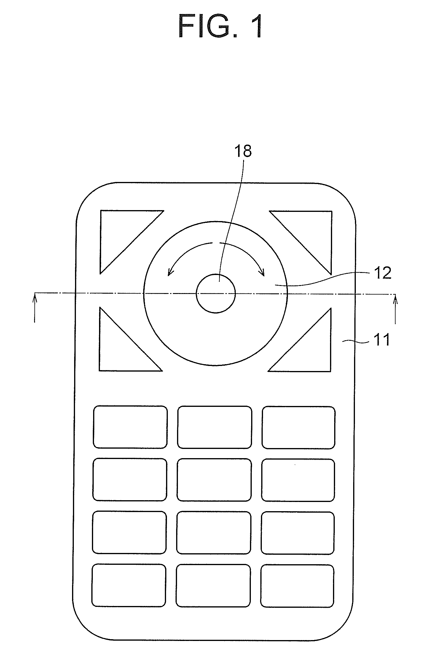
[0022]FIG. 1 is an illustration diagram showing an input device according to the exemplary embodiment of the invention. The input device of the present invention includes a key 12 (hereinafter referred to as an integrated key) surrounding a selection key 18. The selection key 18 is a key for instructing determination of the item selected by a user. The integrated key 12 is a disk-shaped operation key having a hole in the center for arranging the selection key 18. The integrated key (the operation key) 12 acts as a four-direction key which serves as push-buttons (a push-button attitude) at its four positions of the top, bottom, right and left and as a touch key on which a continuous input operation is performed by shifting a finger in a circular motion. An attitude of the integrated key (the operation key) 12 in which the continuous input operation is performed is called as a scroll attitude, with which the integrated key 12 is pressed down, with inclined, along a circumferential direction around the selection key 18. On the integrated key 12, for example, the operation to instruct cursor movements by shifting the finger in a continuous circular motion is performed. Note that the outline shape of the key 12 is a disk-shape, however, the shape is not limited to that. The outline shape of the key 12 may be a multangular shape approximating a disk-shape. In short, as long as the key 12 being independent of the selection key 18 inclines to the top, bottom, right and left directions, in other words, as long as the key 12 functions as push-buttons at its four positions of the top, bottom, right and left, any shapes may be acceptable. Further, the key 12 is so configured to become a push-button in the case where it inclines to the four positions of the top, bottom, right and left, but positions where the key 12 functions as push-buttons are not limited to the four positions of the top, bottom, right and left. The key 12 may be set to function as push-buttons in the case where the key 12 inclines at positions other than the four positions of the top, bottom, right and left. FIG. 1 shows an example in which the input device according to the exemplary embodiment of the invention is equipped on a mobile terminal apparatus. A
display device equipped with the mobile terminal is not shown in FIG. 1. With regard to other keys provided on a housing 11 of the mobile terminal apparatus, the explanation will be omitted. In addition, an application range of the input device according to the exemplary embodiment of the invention is not limited to the mobile terminal apparatus. Any apparatus, which needs to output a plurality of kinds of signals (including ON / OFF) by combining the key 12 and the selection key 18, may be acceptable.
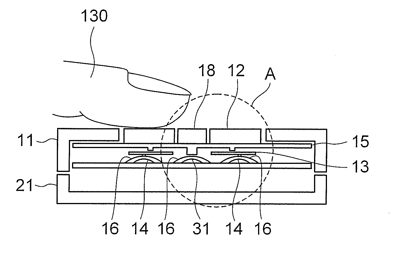
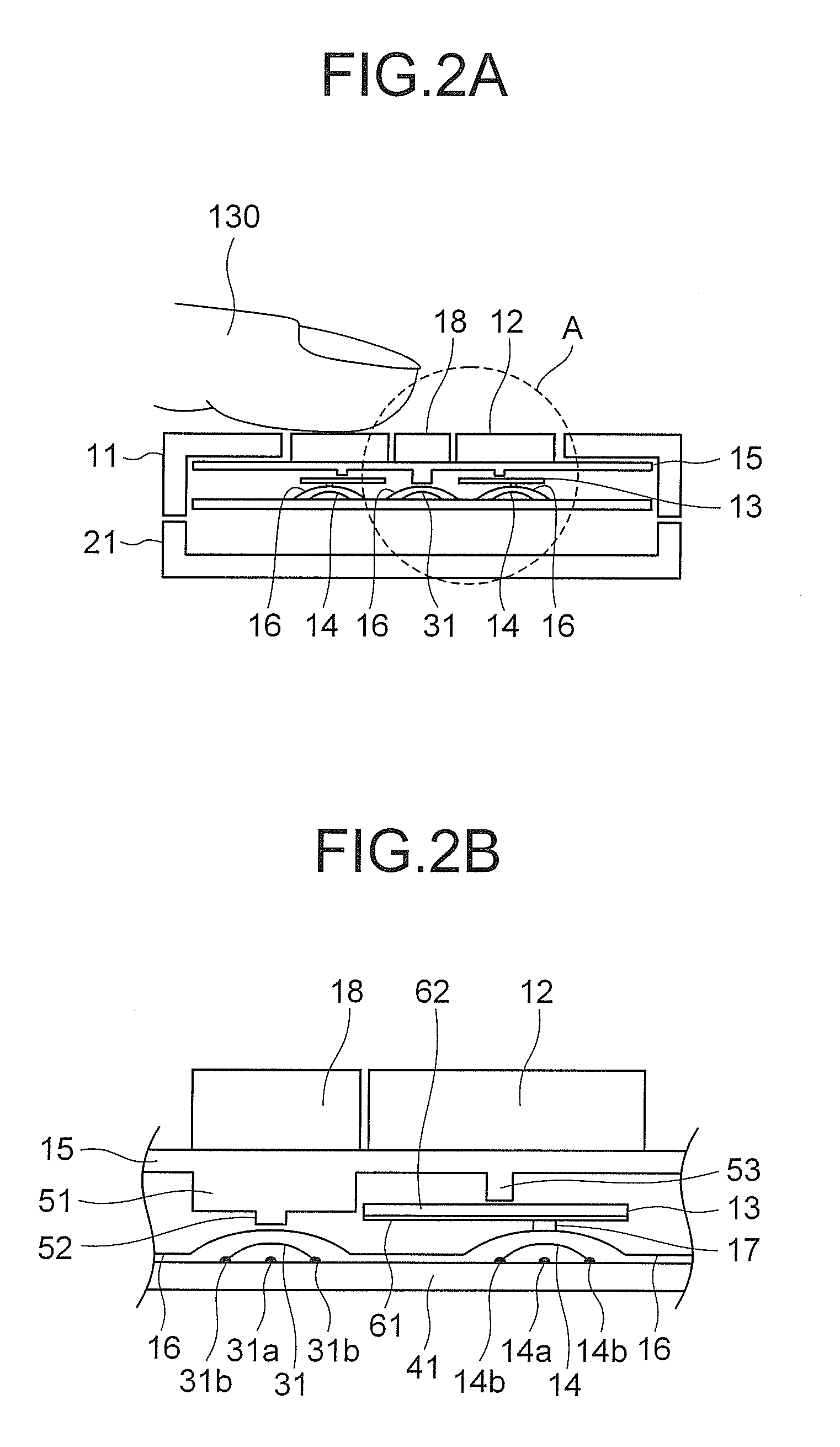
[0023]FIGS. 2A and 2B are cross-section views showing the input device according to the exemplary embodiment of the invention. FIG. 2A is a cross-section view of the input device taken along the chain double-dashed line shown in FIG. 1. FIG. 2B is an enlarged view of a region A shown in FIG. 2A.
[0024]The input device according to the exemplary embodiment of the invention includes: housings (a first housing 11 and a second housing 21) of a mobile terminal apparatus with which the input device itself is equipped; an integrated key 12; a key rubber 15; four metal domes 14 corresponding to the four positions of the top, bottom, right and left of the integrated key 12; and a touch sensor 13 being a sensor in which an electrical value changes in response to a finger shifted on the integrated key 12 (that is, in response to changes of the point on which pressure is applied). The respective metal domes 14 are arranged on a substrate 41. Further, the input device includes a tape (a sheet) 16 for fixing the metal domes 14 on the substrate 41, and includes a projection (hereinafter referred to as an
actuator) 17 at the point corresponding to the tops of the metal domes 14, of the surface of the tape 16 pasted to the metal domes 14. Note that an
actuator is an expedient term, so the
actuator 17 does not operate electrically and it has only to be provided as a projection. As described above, the positions where the key 12 acts as a push-button are not limited to the four positions of the top, bottom, right and left. If the number of positions where the key 12 acts as push-buttons are increased or decreased, the number of the metal domes 14 are also increased or decreased corresponding to the positions.
[0025]Further, a metal dome 31 corresponding to the selection key 18 is provided on the substrate 41. The tape 16 is pasted to the substrate 41 so as to cover not only the four metal domes 14 corresponding to the integrated key 12 but also the metal dome 31 corresponding to the selection key 18, and the tape 16 fixes the metal domes 14 and 31 on the substrate 41. In an example shown in FIG. 2B, respective metal domes 14, the metal dome 31 and the substrate 41 are shown separately from the tape 16 as an expedient, but the tape 16 is pasted to the respective metal domes 14, the metal dome 31 and the substrate 41. In addition, an actuator of the metal dome 31 is not shown in FIG. 2B, but an actuator (a projection) is provided at the point corresponding to the top of the metal dome 31, of the surface of the tape 16.

