Display apparatus, drive control method of display apparatus and manufacturing method of display apparatus

Inactive Publication Date: 2010-09-30
SOLAS OLED LTD
View PDF5 Cites 26 Cited by
  • Summary
  • Abstract
  • Description
  • Claims
  • Application Information

AI Technical Summary

Benefits of technology

[0012]According to the present invention, a display apparatus comprising a touch panel function which can realize a good display quality by inhibiting the contrast f

Problems solved by technology

Therefore, there is a case where display quality is degraded due to contrast being reduced by reflection of external light, attenuation of transmitted light and

Method used


Image

  • Display apparatus, drive control method of display apparatus and manufacturing method of display apparatus
  • Display apparatus, drive control method of display apparatus and manufacturing method of display apparatus
  • Display apparatus, drive control method of display apparatus and manufacturing method of display apparatus

Examples


Example

First Embodiment

Display Apparatus

[0036]First, the display apparatus according to the present invention will be described.

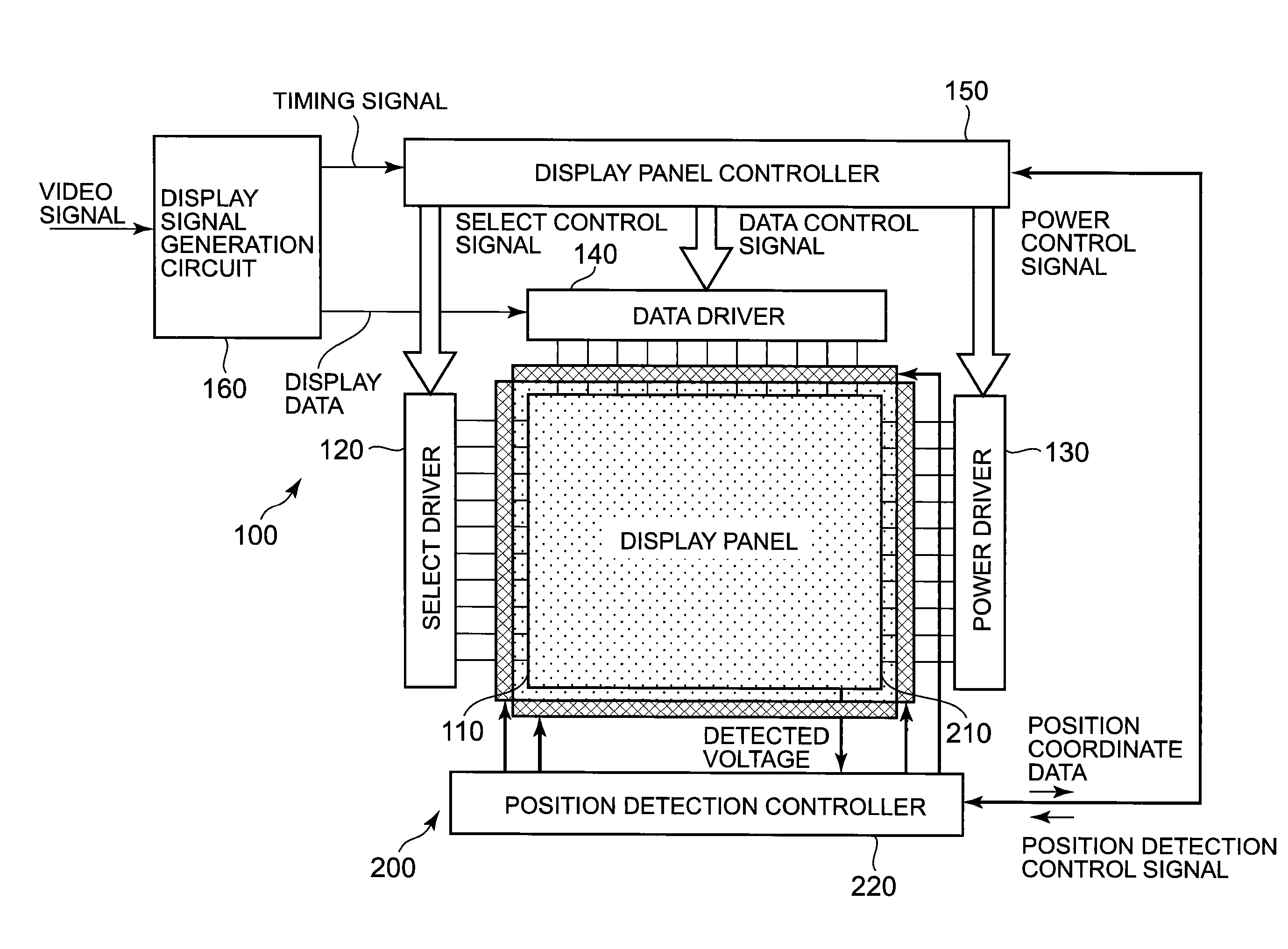
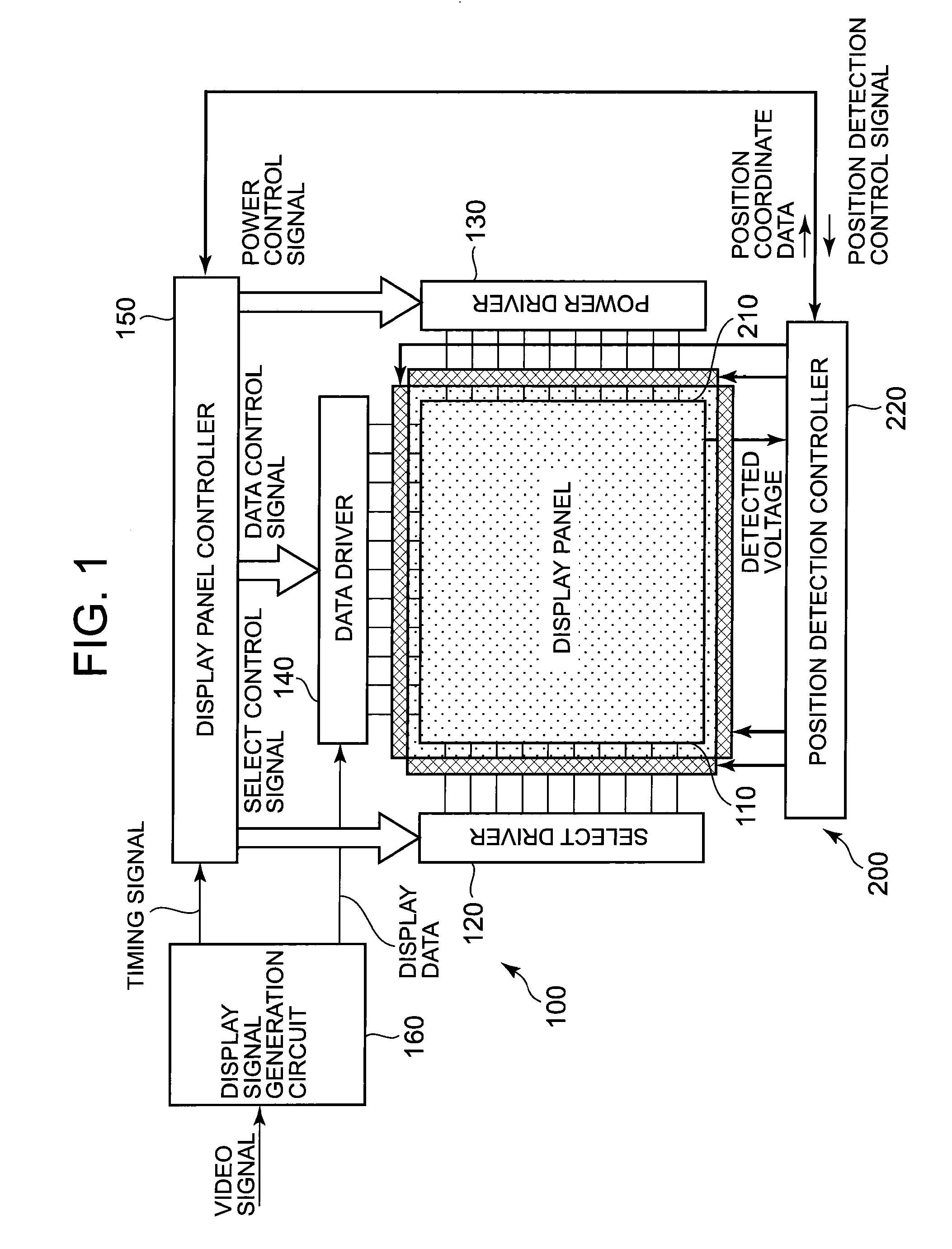
[0037]FIG. 1 is a schematic diagram showing the first embodiment of the display apparatus according to the present invention.

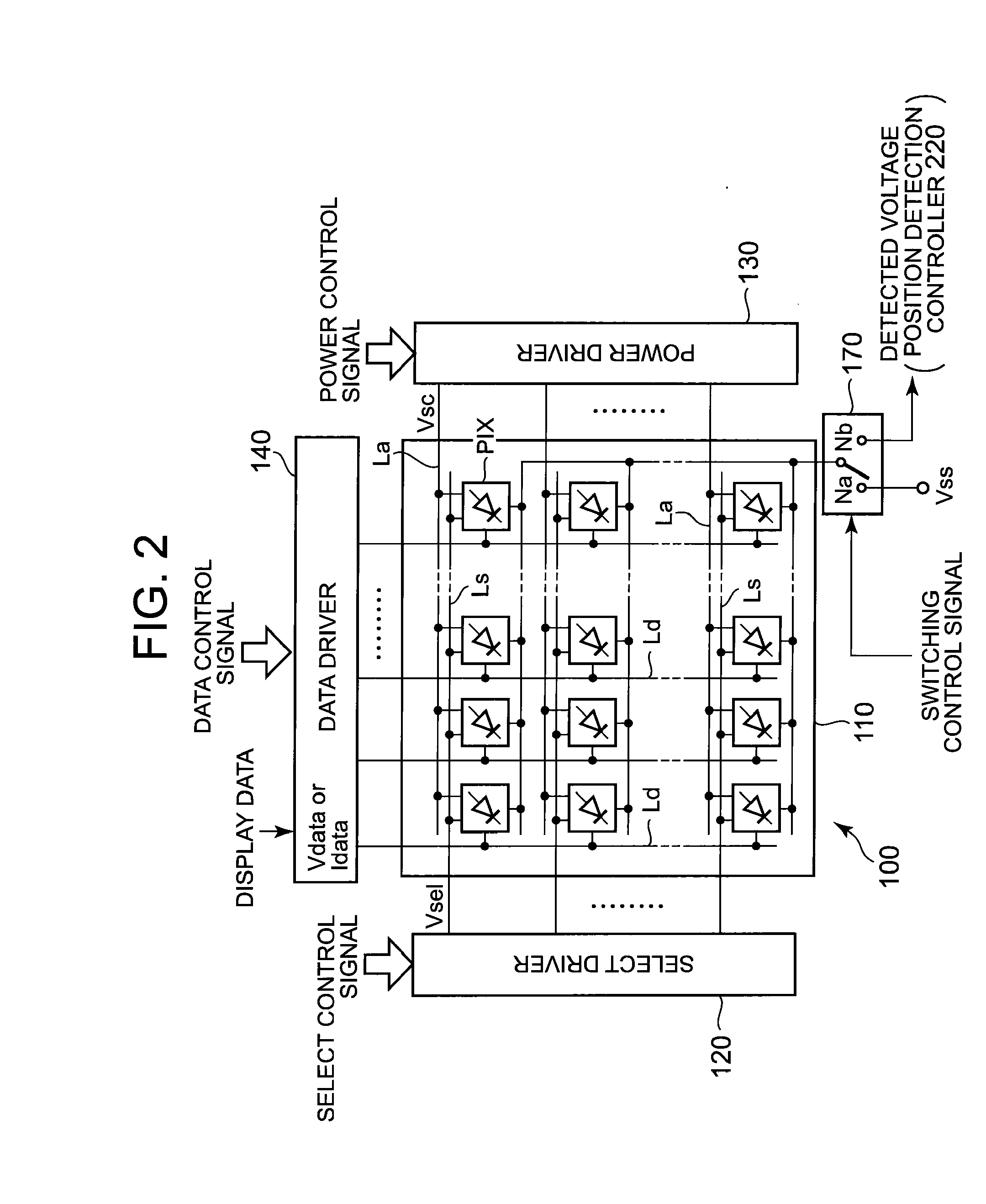
[0038]FIG. 2 is a main structure diagram showing an example of a display panel module which is applied to the display apparatus according to the embodiment.

[0039]In FIG. 1, in order to clarify the arrangement between the display panel module and a position detection module (touch panel module), hatching is carried out for descriptive purposes.

[0040]As shown in FIG. 1, the display apparatus according to the embodiment comprises a display panel module 100 and a position detection module 200.

[0041]As shown in FIGS. 1 and 2, the display panel module 100 roughly comprises a display panel 110, a select driver 120, a power driver 130, a data driver 140, a display panel controller 150, a display signal generation circuit 160 and an electrode connect...

Example

Second Embodiment

[0194]Next, the second embodiment of the display apparatus according to the present invention will be described.

[0195]FIG. 15 is a schematic diagram showing the second embodiment of the display apparatus according to the present invention.

[0196]FIG. 16 is a main structure cross-sectional diagram of the display apparatus according to the embodiment. Here, same symbols are used for structures which are similar to the structures of the above described first embodiment and descriptions are simplified. In FIG. 15, in order to clarify the arrangement between the display panel module and the position detection module, hatching is carried out for descriptive purposes.

[0197]In the above described first embodiment, a case where the plane coordinate circuit 210 of the position detection module 200 is disposed in a visual field side of the display panel 110 and where having a light emitting structure of a top emission type in which a light emitted in each display pixel PIX (org...


PUM

PropertyMeasurementUnit
Pressureaaaaaaaaaa
Flexibilityaaaaaaaaaa
Heightaaaaaaaaaa

Abstract

Disclosed is a display apparatus including a plurality of display pixels formed of a plurality of first electrodes provided in one surface side of a substrate, a second electrode which faces each of the first electrodes and display functional layers which are provided between each of the first electrodes and the second electrode and a resistive film having a predetermined resistivity in which one surface side is provided so as to face the other surface side of the second electrode having a predetermined space above the upper surface of a partition wall layer to define a forming region for each of the display pixels and which is disposed so as to be conductive to the other surface side of the second electrode by a pressure applied from outside, and the second electrode constructing the display pixels is double used as an electrode for detecting a position where the pressure is applied.

Description

BACKGROUND OF THE INVENTION[0001]1. Field of the Invention[0002]The present invention relates to a display apparatus, a drive control method thereof and a manufacturing method thereof. In particular, the present invention relates to a display apparatus comprising a touch panel function, a drive control method thereof and a manufacturing method thereof.[0003]2. Description of the Related Art[0004]Conventionally, a display apparatus which comprises a touch panel function to select operation and to input information by a user directly touching a display screen is used in car navigation systems, automated teller machines (ATM), some personal computers and the like. In recent years, cell phones, portable music players, digital cameras, electronic dictionaries and the like which comprise a touch panel function are being commercialized.[0005]Meanwhile, as a display panel to be applied to the display apparatus comprising such function, conventionally, a liquid crystal display (LCD) panel ha...

Claims


Application Information

Patent Timeline
IPC IPC(8): G06F3/038H05K3/00
CPCY10T29/49117G06F3/0412G06F3/0416G06F3/045G06F3/04164
Inventor TAKEI, MANABU
Owner SOLAS OLED LTD
Why Eureka
Try Eureka