

Spacer forming method and spacer fabricating device
A spacer and corresponding position technology, applied in nonlinear optics, instruments, optics, etc., can solve problems affecting nozzle ejection performance, lower production efficiency, lower display image quality, etc., achieve good display quality and improve quality
- Summary
- Abstract
- Description
- Claims
- Application Information
AI Technical Summary
Problems solved by technology
Method used
Image

Examples
Embodiment Construction
[0056] The specific implementation forms of the present invention will be described below with reference to the accompanying drawings. In addition, this invention is not limited to the following embodiment, Various deformation|transformation is possible according to the technical idea of this invention.
[0057] (first embodiment)
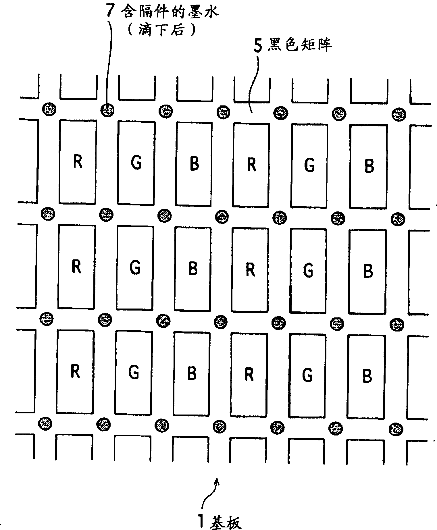
[0058] A liquid crystal panel is constructed by sealing liquid crystals in a gap of several microns formed between a pair of substrates. One of the pair of substrates is formed by forming polarizers, color filters, counter electrodes, alignment films, etc. on a glass substrate. On the other hand, polarizers, pixel electrodes, driving transistors, alignment films, etc. are formed on the glass plate.
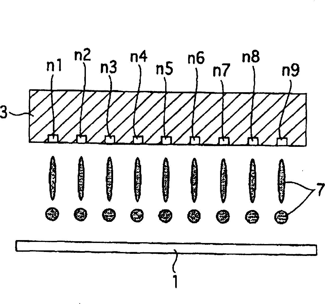
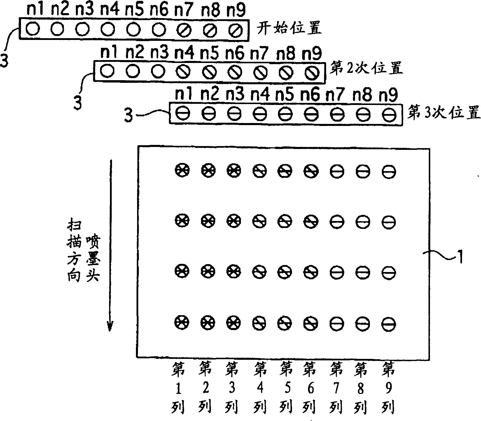
[0059] The two substrates are laminated with their alignment films facing each other. A sealing material for bonding the two substrates into one is applied to one substrate and a spacer is formed on the other substrate not coated with the sealing ...
PUM
 Abstract
Description
Claims
Application Information