Liquid discharge apparatus and method for controlling the same
a technology of liquid discharge apparatus and liquid discharge, which is applied in the direction of power drive mechanism, inking apparatus, printing, etc., can solve the problems of difficulty in securing a retracting space, affecting the stability of the paper sheet,
- Summary
- Abstract
- Description
- Claims
- Application Information
AI Technical Summary
Benefits of technology
Problems solved by technology
Method used
Image
Examples
first embodiment
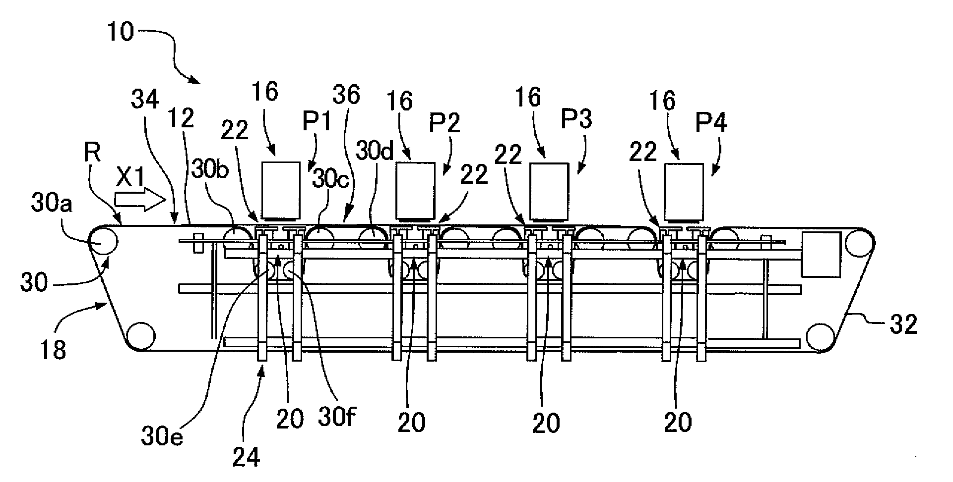
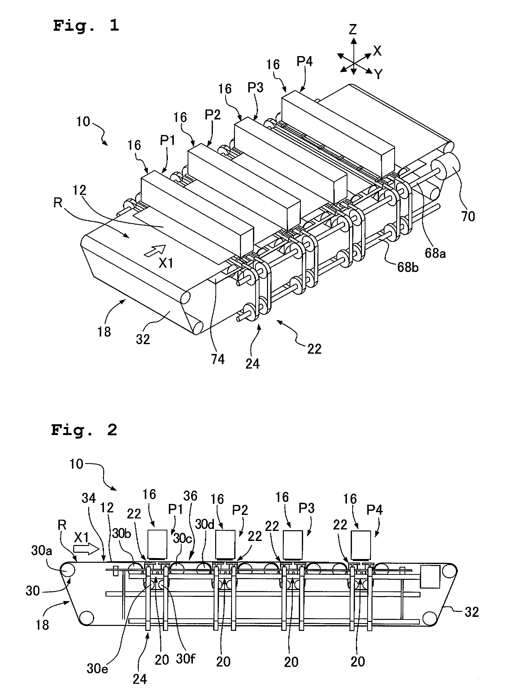
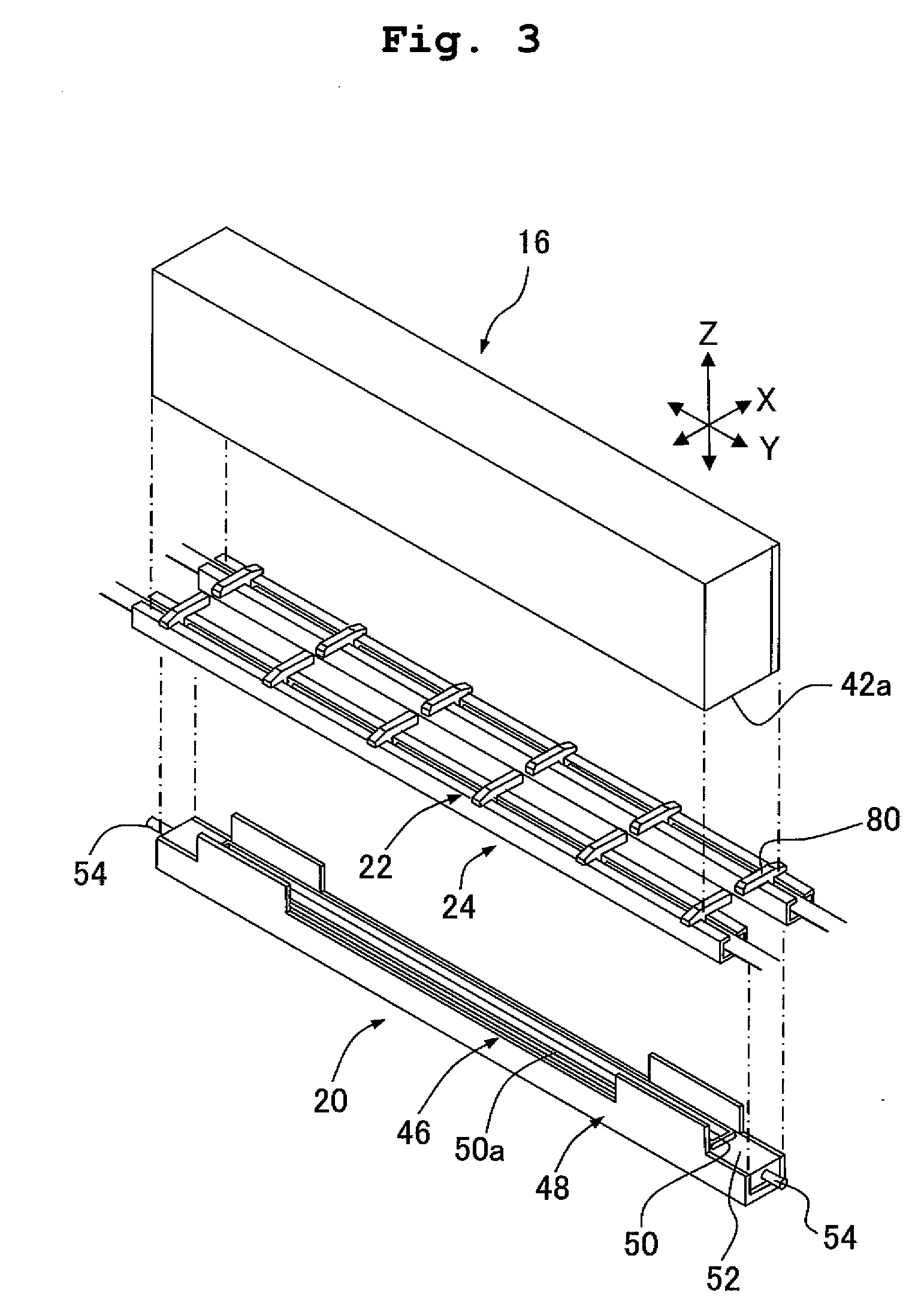
[0033]As shown in FIGS. 1 and 2, an ink discharge apparatus 10 is provided with a plurality of pieces of (four in the embodiment) ink-discharge line head 16 as the “liquid discharge head (head)” having a plurality of nozzles 14 (FIG. 4) through which an ink is discharged toward a paper sheet 12 as the “discharge-objective (object)”; a transporting device 18 which transports the paper sheet 12 to the ink-discharge line heads 16; a platen 22 (FIG. 2) which supports the paper sheet 12 at a position facing the plurality of nozzles 14; and a platen driving device (platen moving device) 24 which drives (moves) the platen 22. Further, the ink discharge apparatus 10 of the embodiment is provided with a cap device 20 (FIG. 2) which covers the plurality of nozzles 14 as necessary. In this embodiment, as shown in FIGS. 1 and 2, a transporting route R for transporting the paper sheet 12 is formed or defined by the transporting device 18; and in the transporting route R, four pieces of the ink-d...
second embodiment
Construction of Ink Discharge Apparatus According to the Second Embodiment
[0068]The ink discharge apparatus of the second embodiment is constructed in a similar manner as the ink discharge apparatus 10 of the first embodiment, except that a spur roller unit 110 is additionally provided on the ink discharge apparatus 10 of the first embodiment as shown in FIGS. 11A and 11B; that a space T is secured for arranging the spur roller unit 110 at a corner portion in the transporting direction X, the corner portion being located below or under the ink-discharge line head 16, as shown in FIG. 12A; and that the height of the platen 22 is adjusted at least in three steps.
[0069]To focus attention to one of the four head positions P1 to P4, as shown in FIG. 12A, one piece of the spur roller unit 110 is provided with respect to one piece of the platen 22 to face or be opposite to the platen 22. The spur roller unit 110 has one spur roller holder 112, six spur rollers 114 and six urging springs 11...
third embodiment
Construction of Ink Discharge Apparatus According to the Third Embodiment
[0074]The ink discharge apparatus of the third embodiment is constructed in a similar manner as the ink discharge apparatus 10 of the first embodiment, except that a wiper 120 is additionally provided on each of the platen belt 66, as shown in FIG. 14.
[0075]The ink discharge apparatus of the third embodiment is capable of performing a cleaning operation by bringing the wiper 120 into contact with the nozzle surface 42a to thereby remove, off the nozzle surface 42a, a stain or dirt such as the ink adhered to the nozzles surface 42a. The wiper 120 has a shape similar to that of the attachment portion 80 shown in FIG. 7, and the wiper 120 is formed, for example, of an elastic material such as rubber, a resin having flexibility (such as elastomer), etc. such that the nozzle surface 42a is hardly damaged or harmed and that the stain can be easily removed. One piece of the wiper 120 is provided on each of the platen ...
PUM
 Abstract
Description
Claims
Application Information
 - R&D
- Intellectual Property
- Life Sciences
- Materials
- Tech Scout
- Unparalleled Data Quality
- Higher Quality Content
- 60% Fewer Hallucinations
Browse by: Latest US Patents, China's latest patents, Technical Efficacy Thesaurus, Application Domain, Technology Topic, Popular Technical Reports.
© 2025 PatSnap. All rights reserved.Legal|Privacy policy|Modern Slavery Act Transparency Statement|Sitemap|About US| Contact US: help@patsnap.com


