Cleaner unit, printing apparatus, and method to clean a printing apparatus

a printing apparatus and cleaning liquid technology, applied in the field of cleaning units, printing apparatuses, printing apparatuses, can solve the problems of increasing the amount of cleaner liquid to be used, requiring a longer period of time for enhanced maintenance operation, and inability to easily remove remaining ink, etc., to achieve enhanced maintenance operation, easy removal, and high specific gravity of coloran

Active Publication Date: 2010-09-30
BROTHER KOGYO KK
View PDF15 Cites 13 Cited by
  • Summary
  • Abstract
  • Description
  • Claims
  • Application Information

AI Technical Summary

Benefits of technology

[0007]The inkjet printer may use white ink, which contains titanium dioxide and therefore has higher specific gravity of colorant with respect to gravities of colorants in the other colored inks. When the white ink is used, the colorant may deposit and remain at lower portions of the ink conveyer tube, and such remaining ink may not easily be removed by the cleaner liquid in the above method. In order to remove the remaining ink, a larger amount of cleaner liquid may be flushed for a longer period of time. Such enhanced maintenance operation requires a longer period of time and increases the amount of cleaner liquid to be used. Further, depending on postures and / or shapes of the ink conveyer tube, even with the enhanced maintenance operation, removing the remaining ink off of the ink conveyer tube sufficiently may still be difficult.
[0008]The removing ability in the cleaning method may be improved, for example, by increasing an amount of surfactant agent in the cleaner liquid. However, before and during the maintenance operation, bubbles may be generated in the cleaner liquid, and the bubbles generated in the highly concentrated surfactant agent tend to remain longer in the ink conveyer tube even after the maintenance operation. When the bubbles remain in the ink conveyer tube, a flow path for the ink is narrowed, and the ink supplying ability of the ink conveyer tube is lowered. Further, the bubbles in the ink conveyer tube can be conveyed to the inkjet head and may cause failure of ink ejection during a printing operation.
[0009]In view of the above drawbacks, the present invention is advantageous in that a cleaner unit to sufficiently clean the print head and the ink conveyer tube in a less complicated manner, is provided. Further, an inkjet printer having such a cleaner unit and a method to clean the inkjet printer are provided.

Problems solved by technology

When the white ink is used, the colorant may deposit and remain at lower portions of the ink conveyer tube, and such remaining ink may not easily be removed by the cleaner liquid in the above method.
Such enhanced maintenance operation requires a longer period of time and increases the amount of cleaner liquid to be used.
Further, depending on postures and / or shapes of the ink conveyer tube, even with the enhanced maintenance operation, removing the remaining ink off of the ink conveyer tube sufficiently may still be difficult.
However, before and during the maintenance operation, bubbles may be generated in the cleaner liquid, and the bubbles generated in the highly concentrated surfactant agent tend to remain longer in the ink conveyer tube even after the maintenance operation.
Further, the bubbles in the ink conveyer tube can be conveyed to the inkjet head and may cause failure of ink ejection during a printing operation.

Method used


Image

  • Cleaner unit, printing apparatus, and method to clean a printing apparatus
  • Cleaner unit, printing apparatus, and method to clean a printing apparatus
  • Cleaner unit, printing apparatus, and method to clean a printing apparatus

Examples


Embodiment Construction

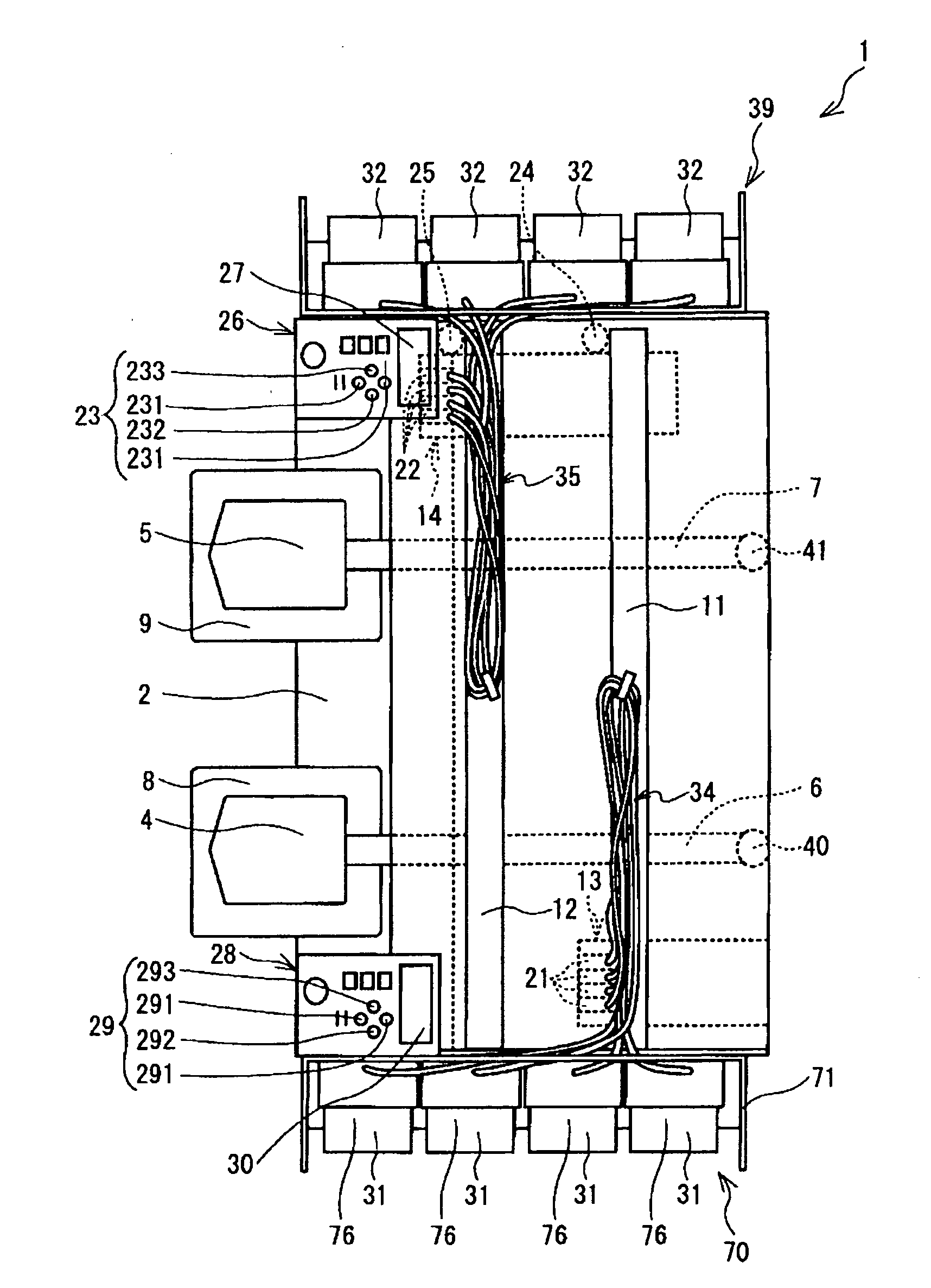
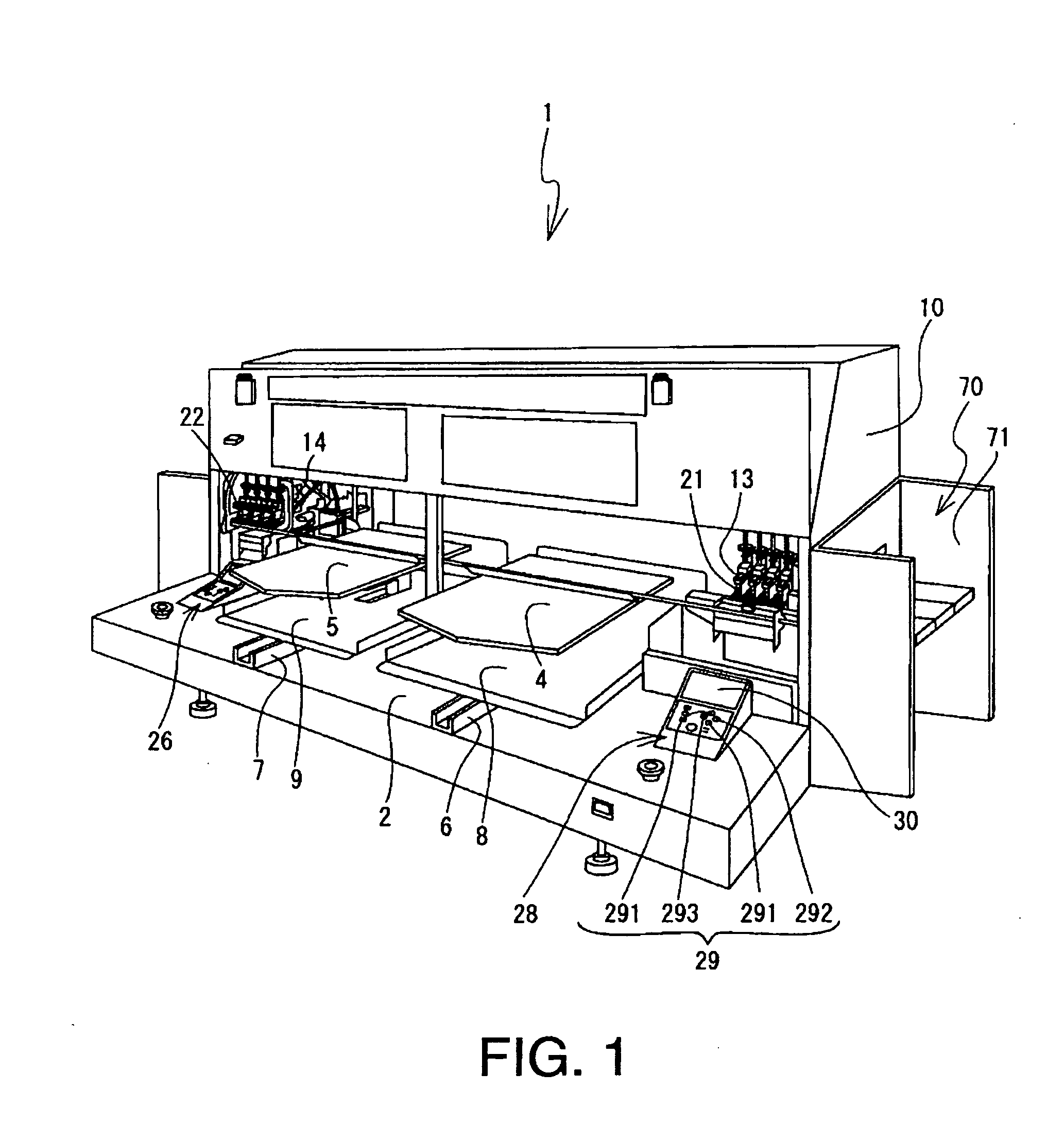
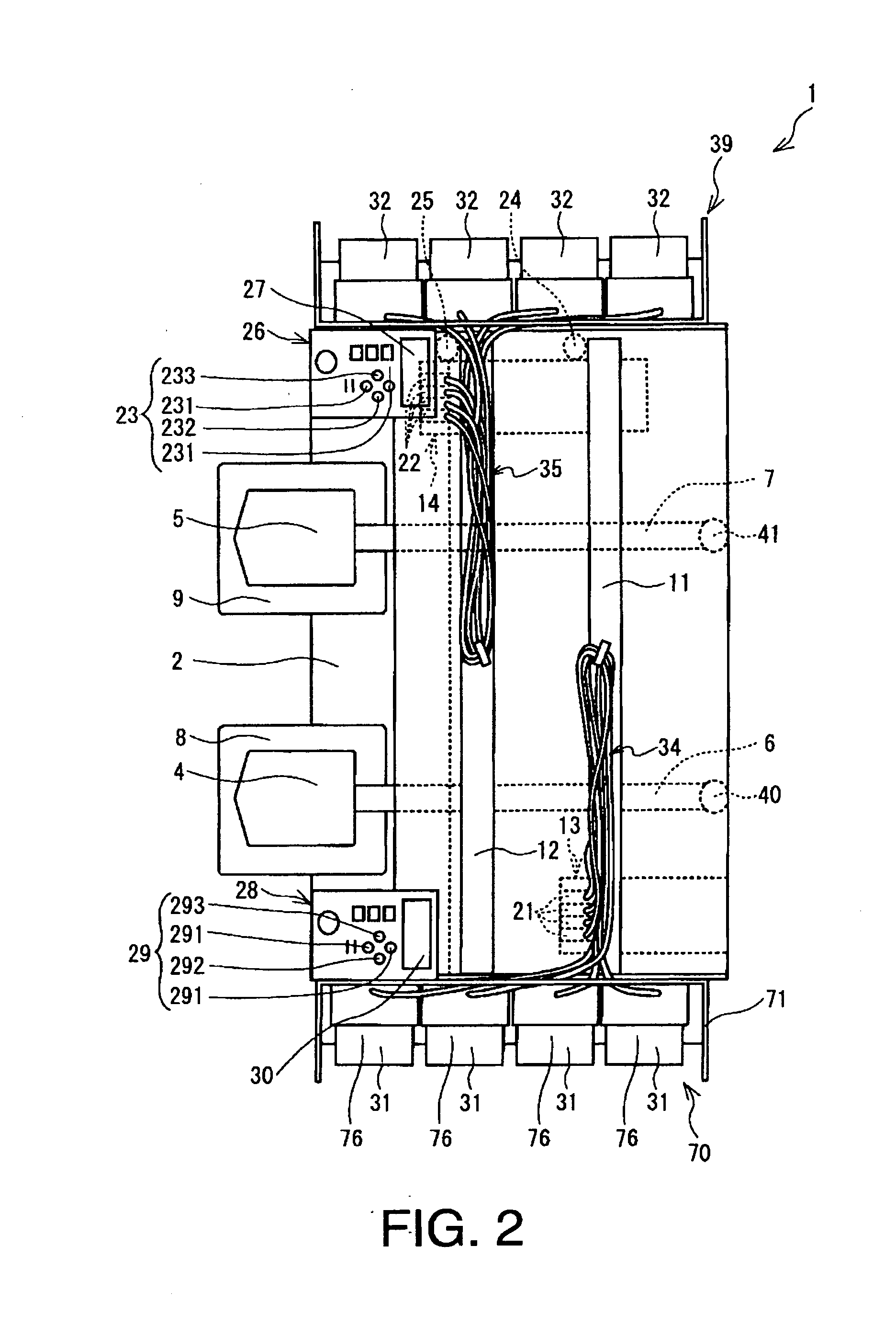
[0030]Hereinafter, an embodiment according to the present invention will be described with reference to the accompanying drawings. Firstly, an overall configuration of an inkjet printer 1 according to the present embodiment will be described with reference to FIGS. 1 through 3. In the following description, a lower-left side, an upper-right side, a lower-right side, and an upper-left side in FIG. 1 correspond to frontward, rearward, rightward, and leftward of the inkjet printer 1 respectively. Further, a right-left direction of the inkjet printer 1 corresponds to a main scanning direction of first print heads 21 and second print heads 22, which will be described later in detail.

[0031]The inkjet printer 1 is a known inkjet printing apparatus, capable of printing an image on a piece of fabric in an inkjet method. As shown in FIGS. 1 and 2, the inkjet printer 1 is provided with a flat base 2 at a bottom and a chassis 10 to cover the entire body of the inkjet printer 1.

[0032]A printing ...


PUM

PropertyMeasurementUnit
specific gravityaaaaaaaaaa
period of timeaaaaaaaaaa

Abstract

A cleaner unit to clean an inkjet head, ejecting ink onto a recording medium, and an ink conveyer tube, conveying the ink to the inkjet head, of an inkjet printer in cleaning liquid, is provided. The cleaner unit includes an air-liquid two-phased cleaner conveyer tube, which conveys air-liquid two-phased cleaner, and a cleaner spout, which is connected to an upstream-side end of the ink conveyer tube and to a downstream-side end of the air-liquid two-phased cleaner conveyer tube with respect to a fluid flow, and through which the air-liquid two-phased cleaner is supplied to the ink conveyer tube.

Description

CROSS REFERENCE TO RELATED APPLICATION[0001]This application claims priority from Japanese Patent Application No. 2009-078411, filed on Mar. 27, 2009, the entire subject matter of which is incorporated herein by reference.BACKGROUND[0002]1. Technical Field[0003]An aspect of the present invention relates to a cleaner unit to clean a print head of a printing apparatus, a printing apparatus having the print head, and a method to clean the printing apparatus.[0004]2. Related Art[0005]Conventionally, an inkjet printer to eject inks onto a recording medium, such as a piece of paper and fabric (e.g., a T-shirt), to print an image has been known. The inkjet printer includes an ink tank to store ink, a print head to eject the ink therefrom, and an ink conveyer tube to supply the ink stored in the ink tank to the print head. When the inkjet printer is left unused for a while, the ink remaining in the inkjet head may dry and adhere thereto. Further, the ink may deposit in the ink conveyer tube...

Claims


Application Information

Patent Timeline
Patent Type & Authority Applications(United States)
IPC IPC(8): B41J2/165B41J2/01B41J2/17B41J2/175C09D11/00C09D11/30
CPCB41J2/1707B41J2/16552
Inventor NIIMI, AKIKOKONDO, KAZUYUKI
Owner BROTHER KOGYO KK
Why Eureka
Try Eureka