Transmission system, repeater and receiver

Inactive Publication Date: 2010-09-30
HITACHI LTD
View PDF10 Cites 32 Cited by
  • Summary
  • Abstract
  • Description
  • Claims
  • Application Information

AI Technical Summary

Benefits of technology

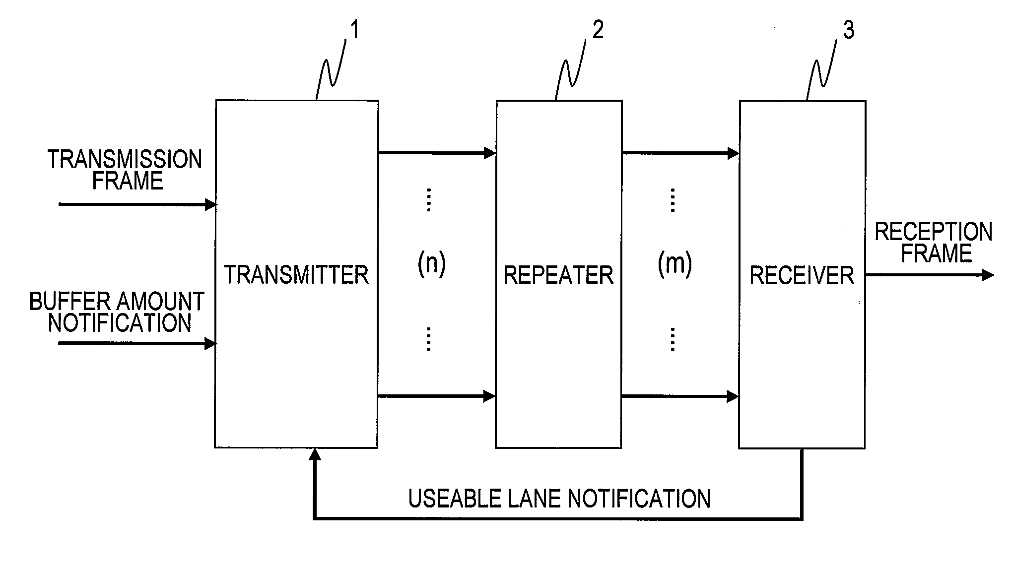
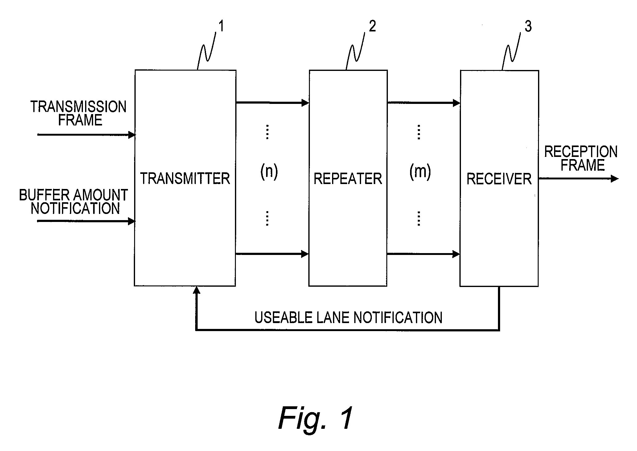
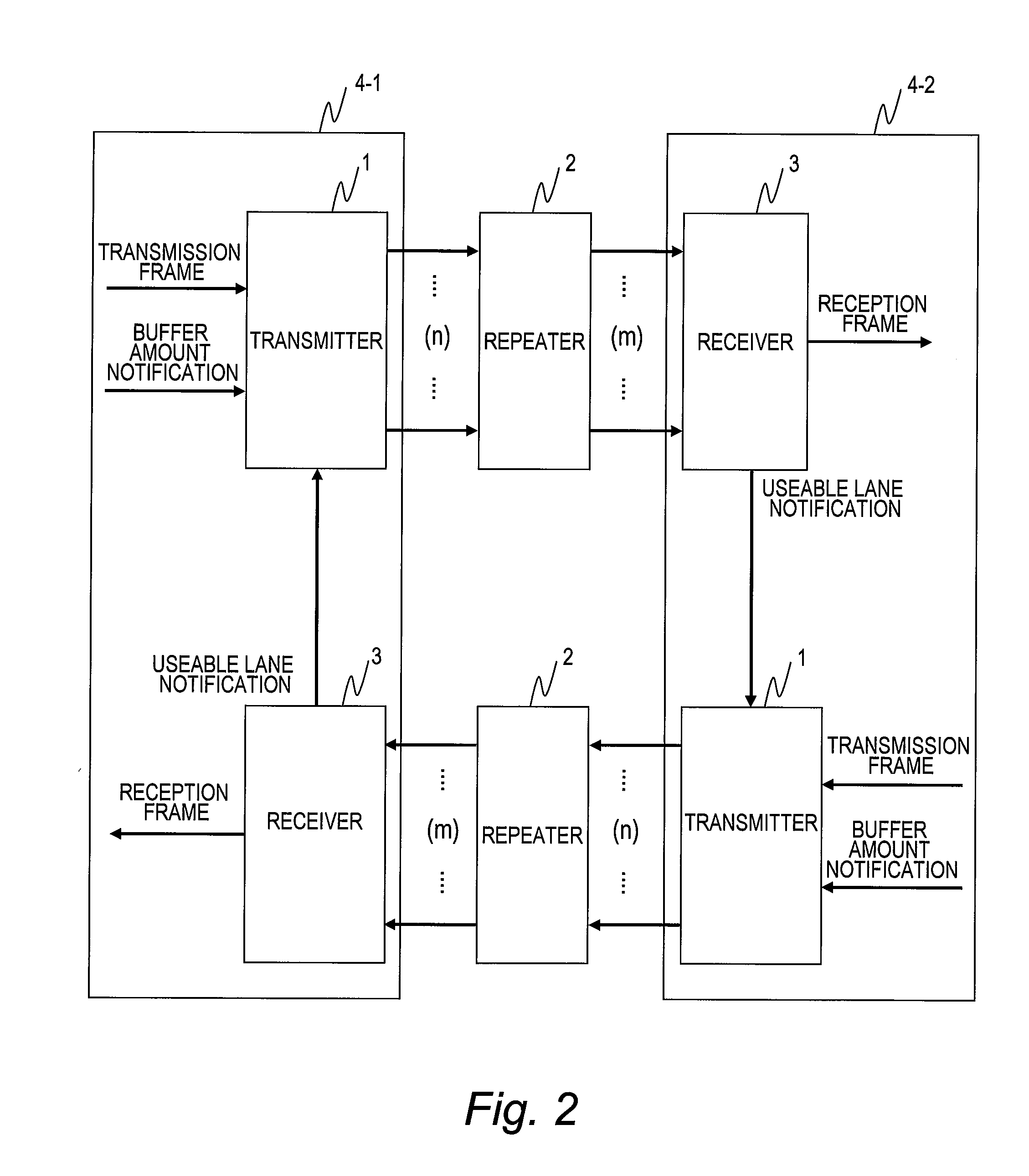
[0008]This invention has been made in view of the above, and it is therefore an object of this invention to provide a transmission system for multi-lane transmission in which the number of lanes can be varied and which is enhanced in fault tolerance by bypassing a failure that has occurred in one of the lanes.
[0010]According to an aspect of this invention, only normal lanes are used while a failure that has occurred in one of transmission lanes is bypassed, and the communication capacity is reduced as well, so that connection is maintained. A transmission system with an enhanced fault tolerance is thus provided.

Problems solved by technology

However, in JP 2006-253852 A and IEEE P802.3ba, a failure in one of the lanes is deemed as a fault of the whole link and the whole link is disconnected.

Method used


Image

  • Transmission system, repeater and receiver
  • Transmission system, repeater and receiver
  • Transmission system, repeater and receiver

Examples


first embodiment

[0035]FIG. 3 is a block diagram illustrating the transmitter 1 according to a first embodiment of this invention.

[0036]The transmitter 1 includes a frame buffer 10, a transmission capacity transfer unit 12, a transmission encoding unit 13, a round robin unit 14, marker inserting units 15 (15-1 to 15-p), and a multiplexer 17.

[0037]The data flow of the transmitter 1 is described first.

[0038]Transmission data is input to the frame buffer 10. A data stream from the receiver 3 is input to the transmission capacity transfer unit 12, the round robin unit 14, and the marker inserting units 15 (15-1 to 15-p).

[0039]The frame buffer 10 outputs data streams to the output source of transmission data and to the transmission capacity transfer unit 12. The transmission capacity transfer unit 12 outputs data streams to the frame buffer 10 and to the transmission encoding unit 13. The transmission encoding unit 13 outputs a data stream to the round robin unit 14.

[0040]The round robin unit 14 outputs ...

second embodiment

[0103]A second embodiment of this invention is described with reference to FIGS. 6 and 7. The second embodiment and the first embodiment take different methods to notify the receiver 3 of a failure that has occurred in a virtual lane. The transmitter 1 of the second embodiment is the same as the transmitter 1 of the first embodiment, and a description thereof is therefore omitted here. The following description of the second embodiment focuses on differences from the first embodiment.

[0104]FIG. 6 is a block diagram illustrating the repeater 2 according to the second embodiment of this invention.

[0105]The repeater 2 of the second embodiment includes the x signal detectors (20-1 to 20-x), the signal monitoring unit 21, the demultiplexer 22, the p block synchronizing units (23-1 to 23-p), the synchronization monitoring unit 24, the failure management unit 25, a PRBS generating unit 28, p selectors (29-1 to 29-p), and the multiplexer 27.

[0106]The repeater 2 of the second embodiment diff...

third embodiment

[0134]A third embodiment of this invention is described with reference to FIGS. 8, 9, and 10. The third embodiment and the first embodiment take different methods to detect a failure that has occurred in a virtual lane. The following description of the third embodiment focuses on differences from the first embodiment.

[0135]FIG. 8 is a block diagram illustrating the transmitter 1 according to the third embodiment of this invention.

[0136]The transmitter 1 includes the frame buffer 10, the transmission capacity transfer unit 12, the transmission encoding unit 13, the round robin unit 14, the marker inserting units 15 (15-1 to 15-p), error correction encoding units (16-1 to 16-p), and the multiplexer 17.

[0137]The transmitter 1 of the third embodiment differs from that of the first embodiment in that the error correction encoding units (16-1 to 16-p) are provided between the marker inserting units (15-1 to 15-p) and the multiplexer 17.

[0138]The data flow of the error correction encoding ...


PUM


Abstract

It is provided a data transmission system comprising a transmitter, a repeater and a receiver. The transmitter and the repeater are coupled through a first transmission path and the receiver and the repeater are coupled through a second transmission path. The transmitter, the repeater and the receiver have virtual lanes. The transmitter demultiplexes the transmission data into as many data streams as a number of useable virtual lanes based on useable lane information. The repeater monitors failures of the transmission lanes of the first transmission path and the virtual lanes. The receiver monitors failures of the transmission lanes of the second transmission path and the virtual lanes, selects the useable virtual lanes, sends to the transmitter the useable lane information, corrects a wrong order of the received data streams and a shift of reception point in the virtual lanes, and restores the demultiplexed data streams into the transmission data.

Description

CLAIM OF PRIORITY[0001]The present application claims priority from Japanese patent applications JP 2009-075845 filed on Mar. 26, 2009, the content of which are hereby incorporated by reference into this application.BACKGROUND OF THE INVENTION[0002]This invention relates to a data transmission system for transmitting data through a transmission path and, in particular, to a data transmission system that is capable of varying the number of lanes in a transmission path.[0003]In the field of long-distance data transmission, the transmission speed of a method that uses a single transmission channel (also called a lane) to transmit data has reached a ceiling and lately it is difficult to enhance the transmission speed any higher. As a way to improve communication band, technologies have been developed in which a plurality of lanes are bundled into a seemingly single link (lane bundling and deskew between lanes of a multi-lane link (multi-lane deskew)) (see, for example, JP 2006-253852 A ...

Claims


Application Information

Patent Timeline
IPC IPC(8): G01R31/08H04L69/14H04L69/40
CPCH04L43/065H04L41/0677H04L1/20H04L41/40H04L43/20
Inventor TOYODA, HIDEHIROMURAI, SHINJI
Owner HITACHI LTD
Why Eureka
Try Eureka