Method and an apparatus for determining the radio frame structure of time division duplex system

a radio frame structure and radio frame technology, applied in the field of mobile communication technologies, can solve the problems of reducing data transmission capacity, affecting system peak rate and transmission efficiency, and reducing transmission efficiency

Active Publication Date: 2010-09-30
DATANG MOBILE COMM EQUIP CO LTD
View PDF3 Cites 109 Cited by
  • Summary
  • Abstract
  • Description
  • Claims
  • Application Information

AI Technical Summary

Benefits of technology

[0069]In the method and apparatus for the coexistence of TDD systems according to the embodiments of the invention, it determines, according to the time slot allocation ratio information of a radio frame in the second TDD system by taking one radio frame as the configuration period, the configuration mode of radio frames in the first TDD system and the time offset of the initiation time of the radio frame relative to the initiation time of the radio frame in the second TDD system, configures the radio frames in the first TDD system according to the configura

Problems solved by technology

In an OFDM system, the CP length determines the anti-multipath capacity of the OFDM system, so a long CP is favorable to overcome multipath interference, but the system overhead may be large, and the relatively large overhead may affect the peak rate and the transmission efficiency of the system, thereby lowering the data transmission capacity.
Therefore, the existing CP length in Type2 may decrease the transmission efficiency.
However, the above configuration metho

Method used


Image

  • Method and an apparatus for determining the radio frame structure of time division duplex system
  • Method and an apparatus for determining the radio frame structure of time division duplex system
  • Method and an apparatus for determining the radio frame structure of time division duplex system

Examples


Embodiment Construction

[0092]The technical solutions of the invention will now be further illustrated in detail by specific embodiments in conjunction with the drawings.

[0093]The process of a transmission method for a TDD system according to an embodiment of the invention is as shown in FIG. 6, which includes:

[0094]Process 601: the network side configures a radio frame structure used for service transmission.

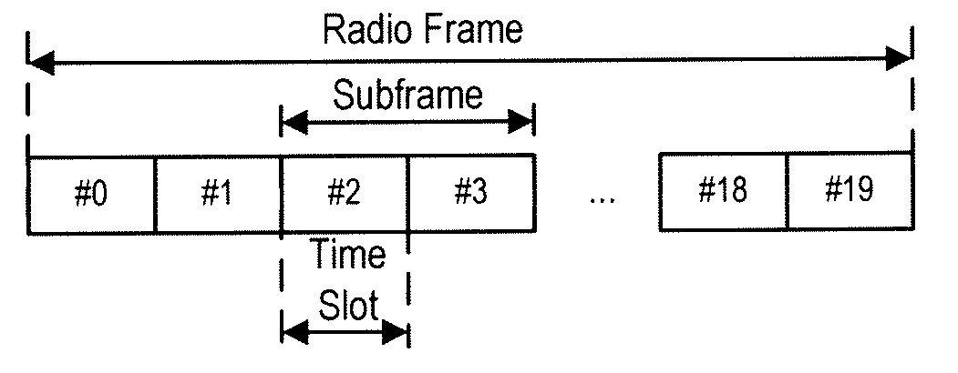
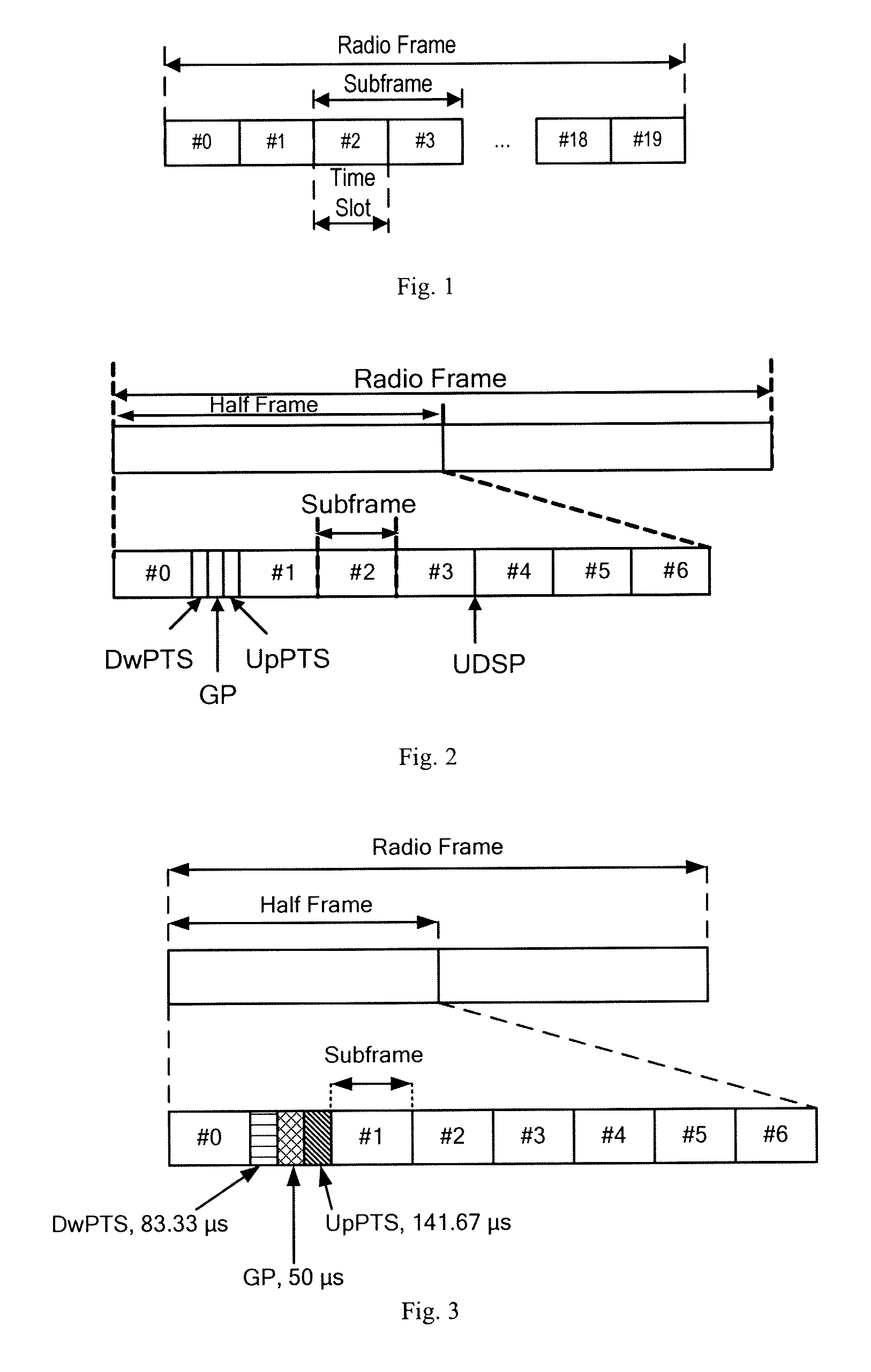
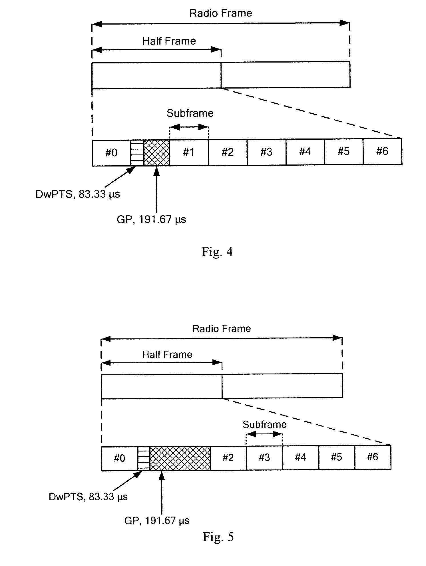
[0095]The radio frame structure is as follows: a radio frame of 10 ms contains 2 half-frames each of 5 ms, each half-frame consists of 8 service time slots each of 0.5 ms and 1 special time slot field of 1 ms, and two consecutive service time slots form a subframe of which the length is 1 ms, and the special time slot field contains 3 special time slots: DwPTS, GP and UpPTS, as shown in FIG. 7.

[0096]The lengths of the 3 special time slots may be configured flexibly via an upper-layer signaling, but the total length of the special time slot field consisting of the 3 special time slots is kept constant ...


PUM


Abstract

A method for determining the radio frame structure of a Time Division Duplex system is disclosed, which comprises: configuring, by the network side, the radio frame structure used for service transmission as containing two half-frames each of 5 ms, wherein each half-frame consists of eight service time slots of 0.5 ms and one special time slot field of 1 ms, two consecutive service time slots form a subframe of which the length is 1 ms, and the special time slot field contains a DwPTS, a GP and an UpPTS; determining the lengths of the DwPTS, the GP and the UpPTS in the special time slot field according to the requirements of the coverage range, and determining the radio frame structure used for service transmission. By reconfiguring the radio frame structure, the invention can flexibly support different coverage ranges, enhance the flexibility of satisfying different service requirements, and implement the coexistence of two types of TDD systems.

Description

CROSS-REFERENCE TO RELATED APPLICATIONS[0001]The present application claims the benefit of priority to International Patent Application No. PCT / CN2008 / 001840 filed 3 Nov. 2008, which further claims the benefits of priorities to Chinese patent Applications No. 200710176799.X filed 2 Nov. 2007, No. 200710177030.X filed 8 Nov. 2007 and No. 200710177132.1 filed 9 Nov. 2007, the contents of which are incorporated herein by reference in their entirety.FIELD OF THE INVENTION[0002]The present invention relates to the field of mobile communication technologies, and in particular to a method and an apparatus for determining a radio frame structure of a Time Division Duplex (TDD) system.BACKGROUND OF THE INVENTION[0003]At present, the 3rd Generation Partnership Project (3GPP) has started up a study project of Long Term Evolution (LTE) of 3G radio interface technology. With the progression of the study, it is determined that the LTE system supports the following 2 types of radio frame structure...

Claims


Application Information

Patent Timeline
IPC IPC(8): H04J3/00H04W72/04
CPCH04W56/003H04B7/2656H04L5/22H04W72/0466
Inventor SUO, SHIQIANGPAN, XUEMINGSUN, SHAOHUIWANG, YINGMINXIE, YONGBINWANG, KETANG, HAI
Owner DATANG MOBILE COMM EQUIP CO LTD
Why Eureka
Try Eureka