Determination of end of life of oil by electrical means

a technology of oil end of life and electrical means, which is applied in the direction of liquid/fluent solid measurement, instruments, machines/engines, etc., can solve the problems constant reduction of the performance of a lubricating fluid during service, and inability to achieve the desired effect of in-service assessment of oil condition

Active Publication Date: 2010-09-30
GM GLOBAL TECH OPERATIONS LLC
View PDF4 Cites 23 Cited by
  • Summary
  • Abstract
  • Description
  • Claims
  • Application Information

AI Technical Summary

Benefits of technology

[0006]The approach described in greater detail below takes advantage of a previously-developed impedance measuring device (or like device) to make on-vehicle, measurements of the electrical impedance of the oil by applying suitable electrical waveforms to the impedance measuring device when the oil is at a working temperature. For example, oil temperatures in a typical hydrocarbon-fueled internal combustion engine are often in the range of about 90° C. to about 110° C. although they may range up to about 150° C. These measurements may be continually made on the oil during engine operation and at a desired operating temperature of the oil. Corresponding resistivity values and permittivity values may be continually determined from such impedance data. The operation of the impedance device and the continuing determination of resistivity values may be managed by an on-vehicle engine control computer or other computing device programmed for such processing.

Problems solved by technology

Oils used as lubrication fluids in internal combustion engines are subject to progressive degradation in use due to exposure to elevated temperatures in an oxidizing environment; high shear stresses; and contamination from combustion products or other sources.
Thus the performance of a lubrication fluid is continually reduced during service until its lubricating properties fail to meet minimum specifications and it must be changed or replaced with new oil.
These analytic measures are therefore well-suited to research assessments of oil quality but are not a preferred approach for in-service assessment of oil condition.
However significantly extending engine oil change intervals requires reliable knowledge of the state of the oil so that the customer may be promptly notified of the need for an oil change when in-service degradation has reduced lubrication performance to minimally acceptable levels.

Method used


Image

  • Determination of end of life of oil by electrical means
  • Determination of end of life of oil by electrical means
  • Determination of end of life of oil by electrical means

Examples


Embodiment Construction

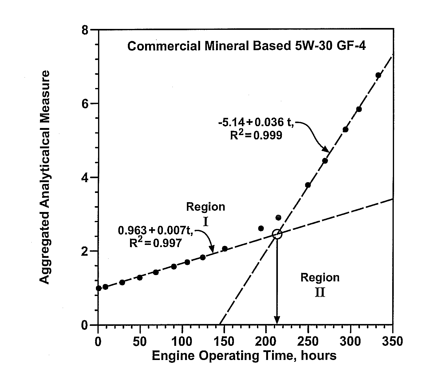
[0017]This invention is a method for determining the quality and useful life of an engine lubrication oil. The method uses a suitable lubricating oil flow-through electrical impedance sensor for monitoring electrical properties of the oil at a normal operating temperature and while in use in an engine or other operating mechanism. And the practice of the method is supported by suitable electronic instrumentation.

[0018]A an example of a suitable cell for measurement or determination of resistivity and permittivity values of an engine oil or other liquid is disclosed in U.S. Pat. No. 7,362,110, “Measurement Cell for Liquids,” Halalay et al and is incorporated into this specification to illustrate the design and use of such a cell. A method of using such a cell in determining and using resistivity values and permittivity values of an engine oil is disclosed in U.S. Pat. No. 7,370,514, “Determining Quality of Oil in Use,” Halalay et al. and is likewise incorporated into this specificati...


PUM

PropertyMeasurementUnit
temperaturesaaaaaaaaaa
temperatureaaaaaaaaaa
temperaturesaaaaaaaaaa

Abstract

Electrical measures of resistivity and permittivity of engine lubricating oil are gathered continuously under normal vehicle engine operating conditions and combined into a composite parameter, the aggregated electrical measure, which, is indicative of engine oil condition and when plotted over the useful life of the oil displays a first linear slope anticipatory of the end of oil life followed by a second, steeper slope indicative of the end of oil life. An algorithm, implementable in an on-vehicle computer, to reliably detect these features is described.

Description

TECHNICAL FIELD[0001]This invention relates to the continuous assessment of the quality and remaining useful life of lubricating oil in an operating internal combustion engine where the oil is subject to continuous deterioration due to its exposure to high temperatures, contamination and shearing loads. The approach entails making continuous measures of the oil's electrical resistance and permittivity, combining these measures in a specified manner and using the resulting combined measure as an indicator of oil life.BACKGROUND OF THE INVENTION[0002]Oils used as lubrication fluids in internal combustion engines are subject to progressive degradation in use due to exposure to elevated temperatures in an oxidizing environment; high shear stresses; and contamination from combustion products or other sources. Thus the performance of a lubrication fluid is continually reduced during service until its lubricating properties fail to meet minimum specifications and it must be changed or repl...

Claims


Application Information

Patent Timeline
Patent Type & Authority Applications(United States)
IPC IPC(8): G01N33/26G01R27/08
CPCF01M11/10G01N33/2888F01M2011/1413F01M2011/14
Inventor HALALAY, ION C.SCHNEIDER, ERIC W.
Owner GM GLOBAL TECH OPERATIONS LLC
Why Eureka
Try Eureka