
Casing for insensitive munitions and process for making same

a technology for munitions and cases, applied in the field of cases for insensitive munitions, can solve the problems of enhancing the severity of damage, difficult and expensive manufacturing, and loss of manpower and capability of our own forces

Active Publication Date: 2010-10-07
IMI SYST LTD
View PDF13 Cites 0 Cited by
  • Summary
  • Abstract
  • Description
  • Claims
  • Application Information

AI Technical Summary

Benefits of technology

[0012]Accordingly, a primary object of the present invention is to provide a tailored, economical and reliable insensitive munitions motor case that will lose its structural integrity upon reaching a predetermined temperature which is below the auto-ignition temperature of the housed propellant, thereby rendering the case incapable of sustaining sufficient internal pressure to destructively detonate the case.

Problems solved by technology

However, this same lethal and / or damaging potential can result in the loss of manpower and capability of our own forces in the event that the munitions is mishandled, subject to fuel fire and / or cook-off conditions, or projectile and / or shock scenarios.
Furthermore, the propagation of the damaging reaction from the initiating munitions to adjacent material and munitions can greatly enhance the severity of damage.
While the prior art motor cases enable some protection against dangerous propellant pressurization, they can be difficult and expensive to manufacture, and often do not provide adequate venting to insure safe release of the propellant energy.

Method used


Image

  • Casing for insensitive munitions and process for making same
  • Casing for insensitive munitions and process for making same
  • Casing for insensitive munitions and process for making same

Examples


Embodiment Construction

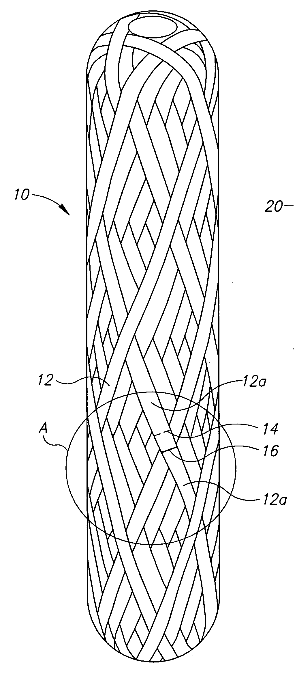
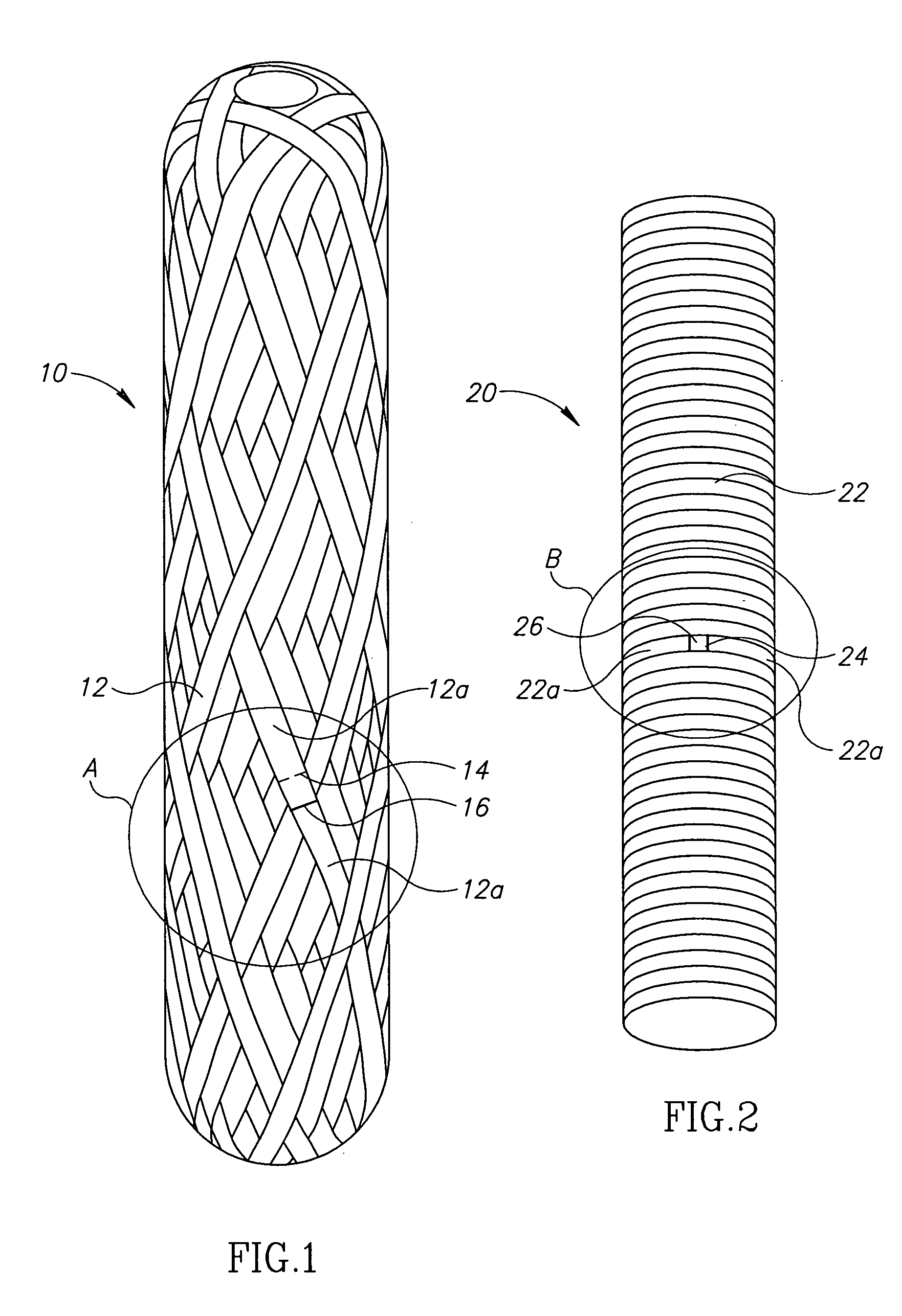
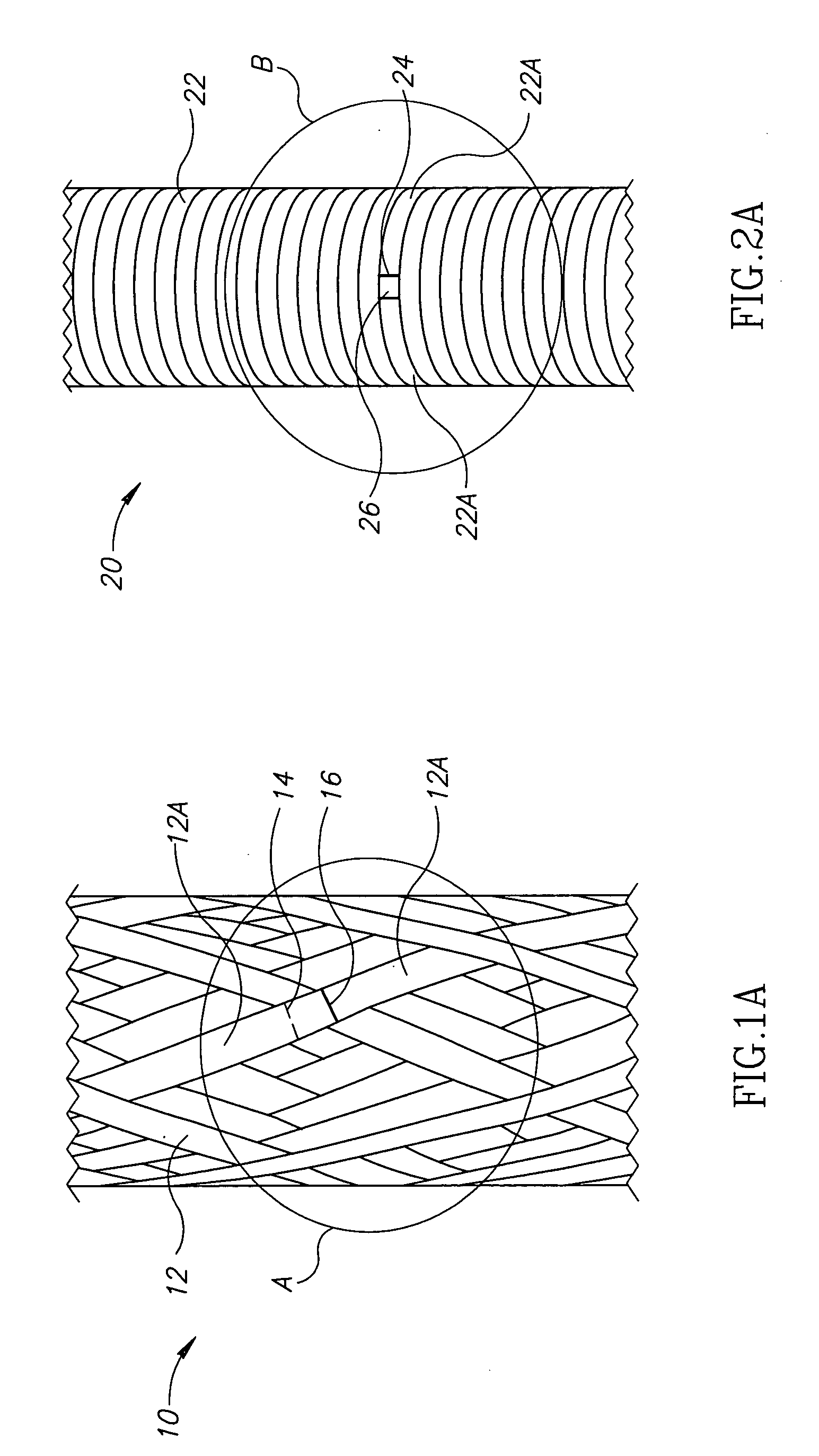
[0037]Referring first to FIGS. 1 and 1A, there is shown an embodiment of an Insensitive Munitions (IM) casing of the present invention. The casing 10 has helically wound reinforcing tape 12. The tape section 12a is cut at 14 and the winding is continued with the rest of the tape 12a overlapping 16 the cut 14 to form a discontinuous section.

[0038]FIGS. 2 and 2A illustrate another casing 20 where the reinforcing tape 22 is wound circumferentially. Tape section 22a is cut at 24 and the winding continued with overlap 26 to form a discontinuous section.

[0039]FIG. 3 shows an IM casing as in FIG. 1 but wherein a patch 38 is placed over the multiple cuts 34, 34a and 34b in tapes 32, 35 and 36 covering and adhering the discontinuous strips of tape together.

[0040]FIG. 4 show still another embodiment of an IM casing similar to that of FIG. 2, but wherein a patch 48 is placed over the multiple cuts 44, 44a, 44b, 44c and 44d, covering and adhering the discontinuous sections of tapes 42, P 42a, 4...


PUM

PropertyMeasurementUnit
Temperatureaaaaaaaaaa
Lengthaaaaaaaaaa
Adhesivityaaaaaaaaaa

Abstract

An insensitive munitions casing, such as a motor case, for housing a propellant charge is disclosed. The casing is formed by winding, wrapping or rolling a fiber, tape or sheet of material such that the casing has a plurality of reinforcing layers. At least some of the reinforcing layers have discontinuous interfaces. Other reinforcing layers may overlap the discontinuous interfaces. The reinforcing layers are coated with adhesive bonding material for adhering the reinforcing layer to itself and bonding the discontinuous interfaces. The adhesive bonding material has a bond-strength breakdown temperature which is below the auto-ignition temperature of the propellant charge. Once the bond strength breakdown temperature of the adhesive is reached, the bond fails at the discontinuous interface, thereby enabling release of propellant charge pressurization.

Description

FIELD OF INVENTION[0001]The present invention relates to a composite motor case and, more particularly, to a case munitions motor that is constructed to structurally degrade when exposed to an abnormally high temperature below the auto-ignition temperature of an encased propellant.BACKGROUND OF THE INVENTION[0002]The destructive capability of explosive munitions is intended to be directed against an aggressor. However, this same lethal and / or damaging potential can result in the loss of manpower and capability of our own forces in the event that the munitions is mishandled, subject to fuel fire and / or cook-off conditions, or projectile and / or shock scenarios. Furthermore, the propagation of the damaging reaction from the initiating munitions to adjacent material and munitions can greatly enhance the severity of damage.[0003]Various munitions motor cases provided with fire exposure safety features are known in the patented prior art.[0004]U.S. Pat. No. 3,665,857 discloses a rocket mo...

Claims


Application Information

Patent Timeline
IPC IPC(8): F02K9/38B32B38/04
CPCF02K9/34F02K9/38Y10T428/1321F05D2300/603Y10T156/1062F42B39/20
Inventor CHEREVATSKY, ABEL
Owner IMI SYST LTD
Learn More