Regenerative braking device and vehicle provided with regenerative braking device

a regenerative braking and braking device technology, which is applied in the direction of braking systems, cycle brakes, cycle equipments, etc., can solve the problems of operator distress, difficulty in changing the regeneration amount, and difficulty in operating the brake lever, so as to facilitate the adjustment of the regenerative

Inactive Publication Date: 2010-10-07
KK TOSHIBA
View PDF6 Cites 39 Cited by
  • Summary
  • Abstract
  • Description
  • Claims
  • Application Information

AI Technical Summary

Benefits of technology

[0011]According to the above-mentioned configuration, it is possible to provide a regenerative braking device for a vehicle that is capable of appropria

Problems solved by technology

In the above-mentioned regenerative braking device, when the brake is operated by the regeneration switch, it is difficult to change the regeneration amount so that a braking amount desired by the operator can be obtained.
Further, in the case of the device in which the regeneration amount is controlled by the operation amount of the brake lever, the range of the operatio

Method used


Image

  • Regenerative braking device and vehicle provided with regenerative braking device
  • Regenerative braking device and vehicle provided with regenerative braking device
  • Regenerative braking device and vehicle provided with regenerative braking device

Examples


first embodiment

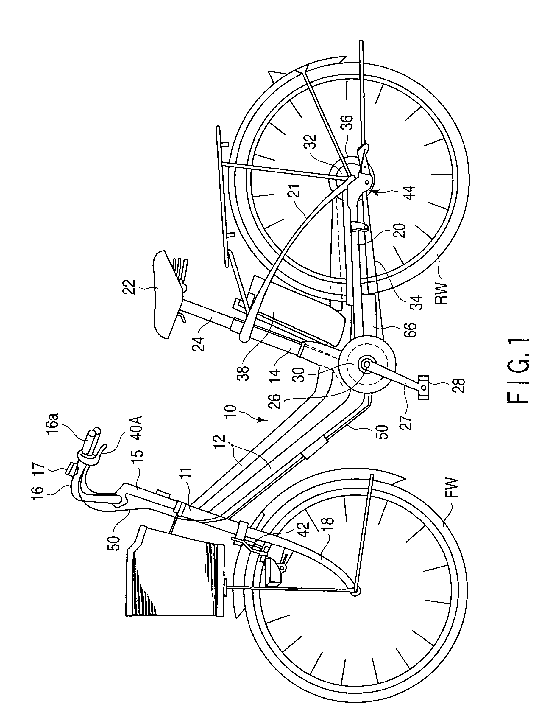
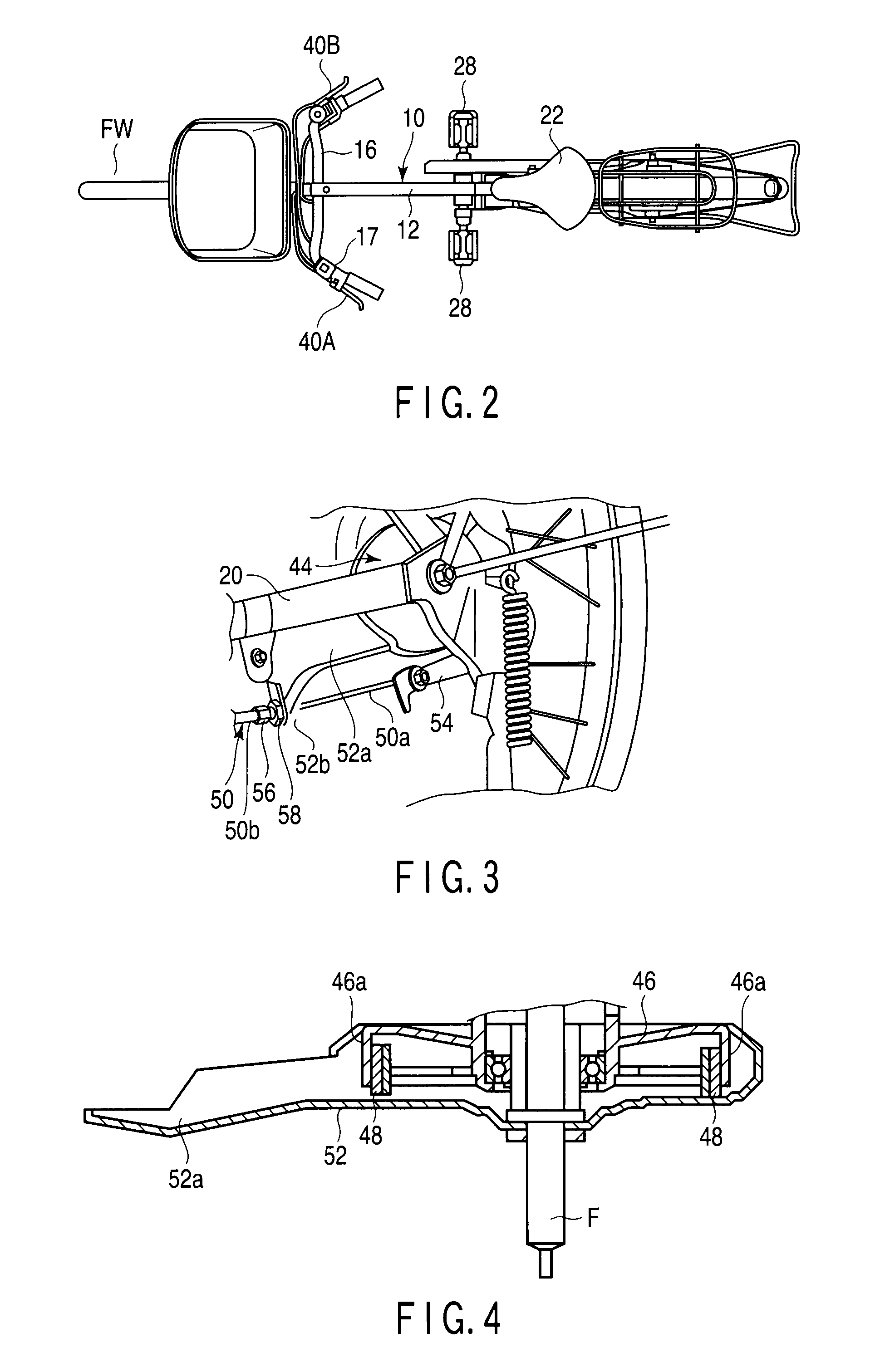
[0041]FIG. 1 shows an electric power assisted bicycle as a vehicle drive device and electric-powered vehicle provided with a regenerative braking device according to a first embodiment. The electric power assisted bicycle comprises a body frame 10, and the body frame comprises a head pipe 11 positioned in the front part of the body, down pipes 12 extending downwardly / rearwardly from the head pipe 11, and seat post 14 upwardly rising from the vicinity of an end part of each of the down pipes 12. A handle post 15 of a handle 16 is rotatably inserted into an upper part of the head pipe 11, and a front fork 18 coupled to the handle post 15 is supported at a lower part of the head pipe 11. A front wheel FW is rotatably and axially supported at lower ends of the front fork 18.

[0042]A pair of right and left chain stays 20 rearwardly extends from a lower end part of the seat post 14, and a rear wheel RW is axially supported between end parts of the chain stays 20. A pair of right and left s...

second embodiment

[0071]Next, a regenerative braking device according to a second embodiment of the present invention will be described. FIG. 8 is a cross-sectional view showing the regenerative braking device according to the second embodiment. It should be noted that in the second embodiment, the same parts as those in the first embodiment are denoted by the same reference symbols as those in the first embodiment, and a detailed description of them is omitted.

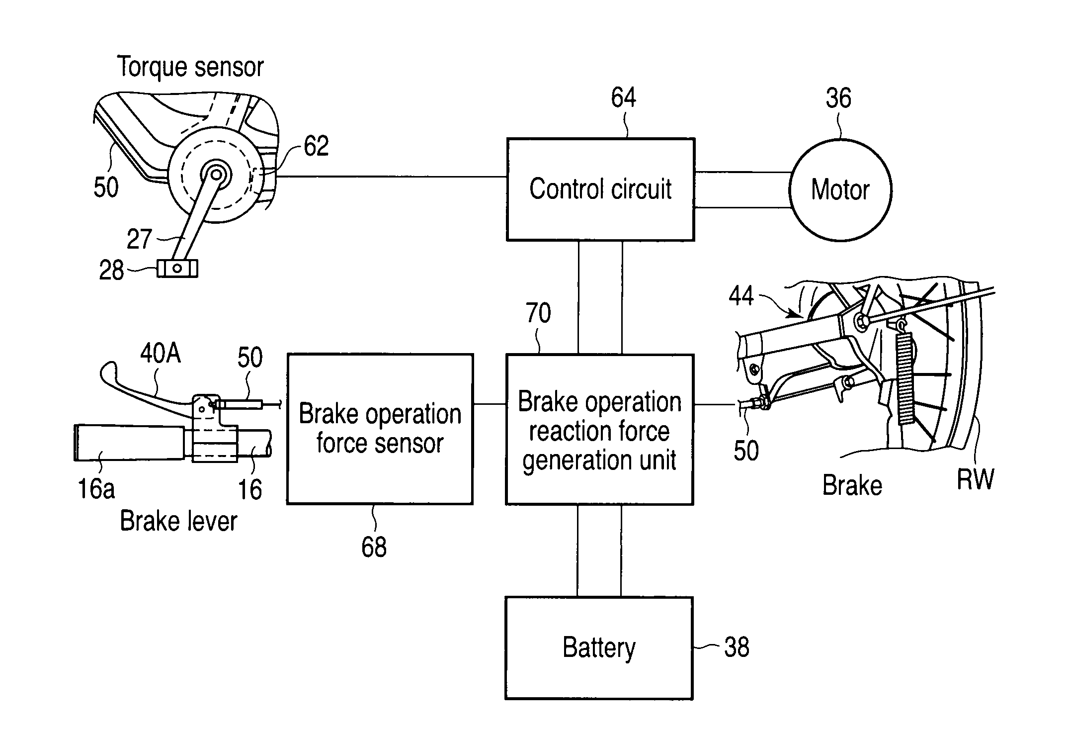
[0072]According to this embodiment, a regenerative braking device 66 is applied to an electric-powered vehicle in which an operation amount of the brake lever is transmitted to a braking mechanism by means of hydraulic pressure. The regenerative braking device 66 comprises a brake operation force sensor 68, and a reaction force generator 70. The brake operation force sensor 68 includes a pressure sensor 74 arranged directly inside the brake piping 86, and the pressure sensor 74 detects the pressure of a working fluid in the brake piping 86.

[00...

third embodiment

[0077]Then, a regenerative braking device according to a third embodiment of the present invention will be described. FIG. 9 is a cross-sectional view showing a regenerative braking device according to the third embodiment. It should be noted that in the third embodiment, the same parts as the first embodiment are denoted by the same reference symbols as the first embodiment, and a detailed description of them are omitted.

[0078]As shown in FIG. 9, the regenerative braking device 66 comprises a brake operation force sensor 68, and a reaction force generator 70, and is provided between a brake lever and a braking mechanism. In this embodiment, the case where an operation of the brake lever is transmitted to the braking mechanism by a brake wire 50 will be described.

[0079]The brake operation force sensor 68 is arranged on the brake lever side of the reaction force generator 70, and detects tension generated in the brake wire 50. The brake operation force sensor 68 is provided with, for...


PUM


Abstract

A regenerative braking device includes a braking mechanism configured to apply a braking force to a wheel, a brake operation section configured to generate a brake operation amount, a brake operation amount transmission section configured to transmit the brake operation amount from the brake operation section to the braking mechanism, a brake operation force sensor configured to detect a brake operation force of the brake operation amount transmission section, a drive device configured to apply a drive force to the wheel, and apply, at an operation time of the brake operation section, a regenerative braking force according to the brake operation force detected by the brake operation force sensor to the wheel, and a reaction force generator configured to apply a brake operation reaction force in accordance with a regeneration amount from the drive device to the brake operation amount transmission section.

Description

CROSS-REFERENCE TO RELATED APPLICATIONS[0001]This application is based upon and claims the benefit of priority from prior Japanese Patent Applications No. 2009-090403, filed Apr. 2, 2009; and No. 2009-285388, filed Dec. 16, 2009, the entire contents of both of which are incorporated herein by reference.BACKGROUND[0002]1. Field[0003]An embodiment of the present invention relates to a regenerative braking device used for an electric-powered vehicle provided with a motor, such as an electric power assisted bicycle, electric motorcycle, electric motorcar, and the like, and a vehicle provided with the device.[0004]2. Description of the Related Art[0005]In general, an electric power assisted bicycle is provided with a motor configured to assist driving of a wheel, and the torque of the motor is controlled in accordance with the pedaling torque. At the braking time of the electric power assisted bicycle, regenerative electric power can be obtained from the motor. There is proposed an elect...

Claims


Application Information

Patent Timeline
IPC IPC(8): B60K1/00B60T8/17
CPCB60L7/18B60L11/1801B60L11/1877B60L2200/12B60L2250/24B60T13/586B60L11/007B62M6/45B62M6/50B62M6/60Y02T10/7005Y02T10/705B62L3/00B60L50/20B60L50/53B60L50/66Y02T10/70
Inventor HOSHINO, MASAYUKI
Owner KK TOSHIBA
Why Eureka
Try Eureka