Mould carrier unit with controlled nozzle

a technology of nozzle and carrier unit, which is applied in the direction of auxillary shaping apparatus, manufacturing tools, ceramic shaping apparatus, etc., can solve the problems of contaminating the immediate vicinity, not being able to guarantee, and present contamination risk, so as to improve the coordination of the movement of the bell

Active Publication Date: 2010-10-07
SIDEL PARTICIPATIONS SAS
View PDF6 Cites 22 Cited by
  • Summary
  • Abstract
  • Description
  • Claims
  • Application Information

AI Technical Summary

Benefits of technology

[0012]The present invention proposes an improvement which makes it possible to improve this type of blow-moulding installation, to make it more flexible, and which also makes it possible to resolve the problems encountered on the mould carrier units, as detailed in the aforementioned documents.
[0013]Firstly, the object of the present invention is to obtain maximum security in terms of the lifting of the bell of the nozzle, relative to a conventional control of the pneumatic type and the invention makes it possible, therefore, to inhibit the risks of collision between the transfer clamps for the moulded containers, in particular, and said nozzle bell.
[0014]According to a preferred embodiment, the present invention makes it possible to eliminate the control of the movement of lifting and lowering the bell, such as for example the control via a pneumatic actuator as disclosed in the aforementioned document FR 2 876 942. This may, in this case, achieve significant advantages in terms of maintenance of the mould carrier unit due to the elimination of the solenoid valve and cables connected to the power supply of the actuator for manoeuvring the bell; it also provides more accessibility to said mould carrier unit due to the elimination of this control of the actuator for manoeuvring the nozzle bell.

Problems solved by technology

However, in the case of blow-moulding installations in which the mould carrier unit uses a control with a cam system, as detailed in the aforementioned document, risks of contamination are present due to the use of mechanisms which require a minimum amount of maintenance and, in particular, lubrication of the moving parts, hence the presence of lubricants, grease or the like, capable of contaminating the immediate vicinity of the mould and the impression of the container.
This control does not make it possible to guarantee the position of the bell of the blowing nozzle relative to the upper surface of the mould, during its movement for shifting it from the active position to the inactive position.
These different types of control of the bell of the nozzle also do not allow the alteration, depending on the dimensions of the preforms, of the distance which separates the free edge of the bell from the inlet surface of the mould and, as a result, they do not offer the flexibility which is expected nowadays for this type of installation.

Method used


Image

  • Mould carrier unit with controlled nozzle
  • Mould carrier unit with controlled nozzle
  • Mould carrier unit with controlled nozzle

Examples


Embodiment Construction

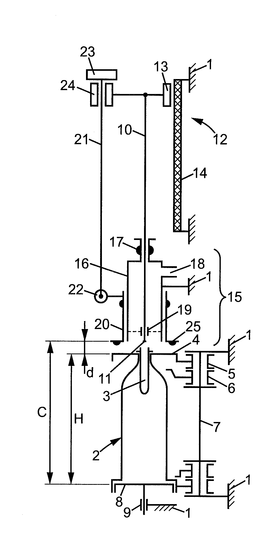
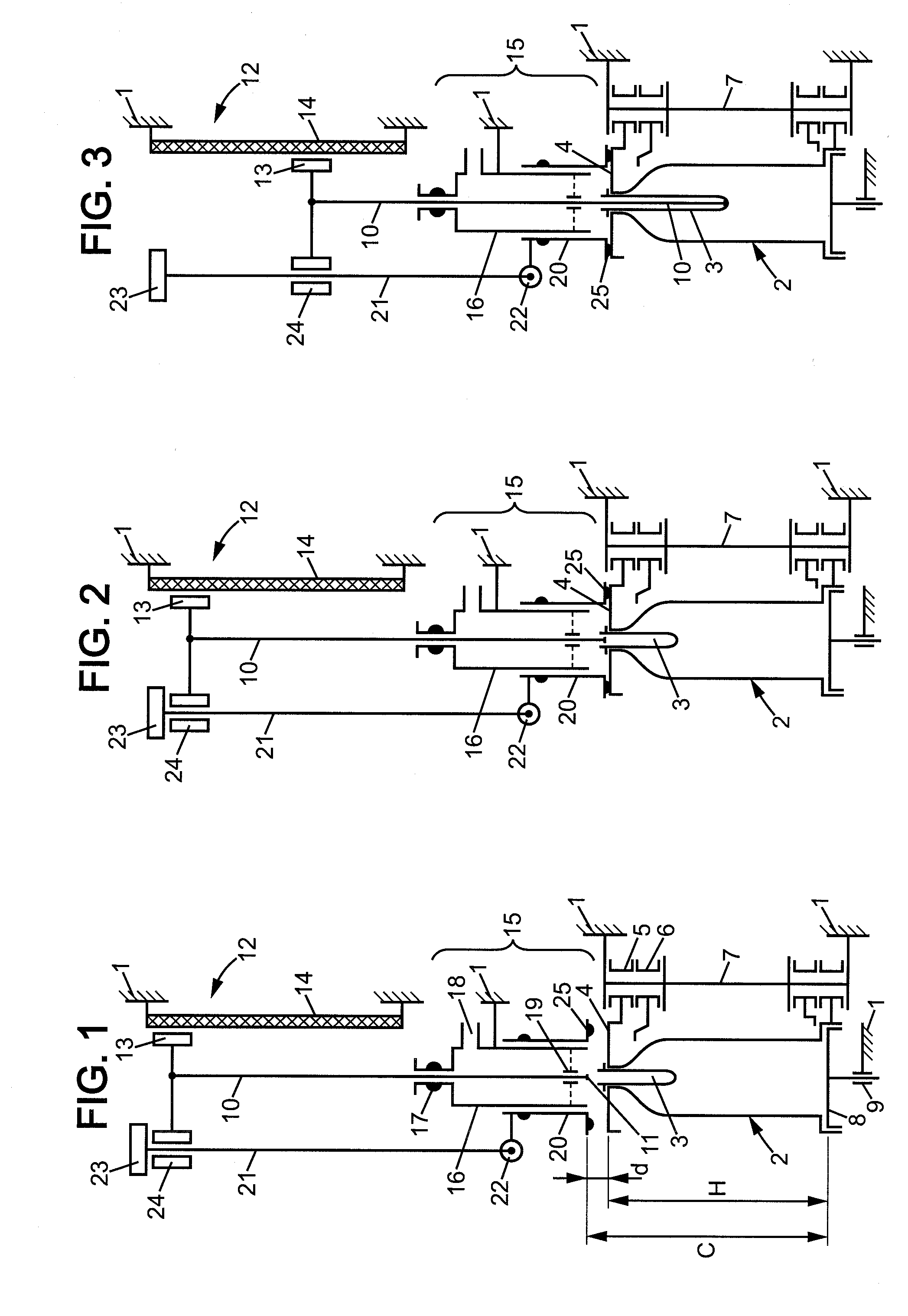
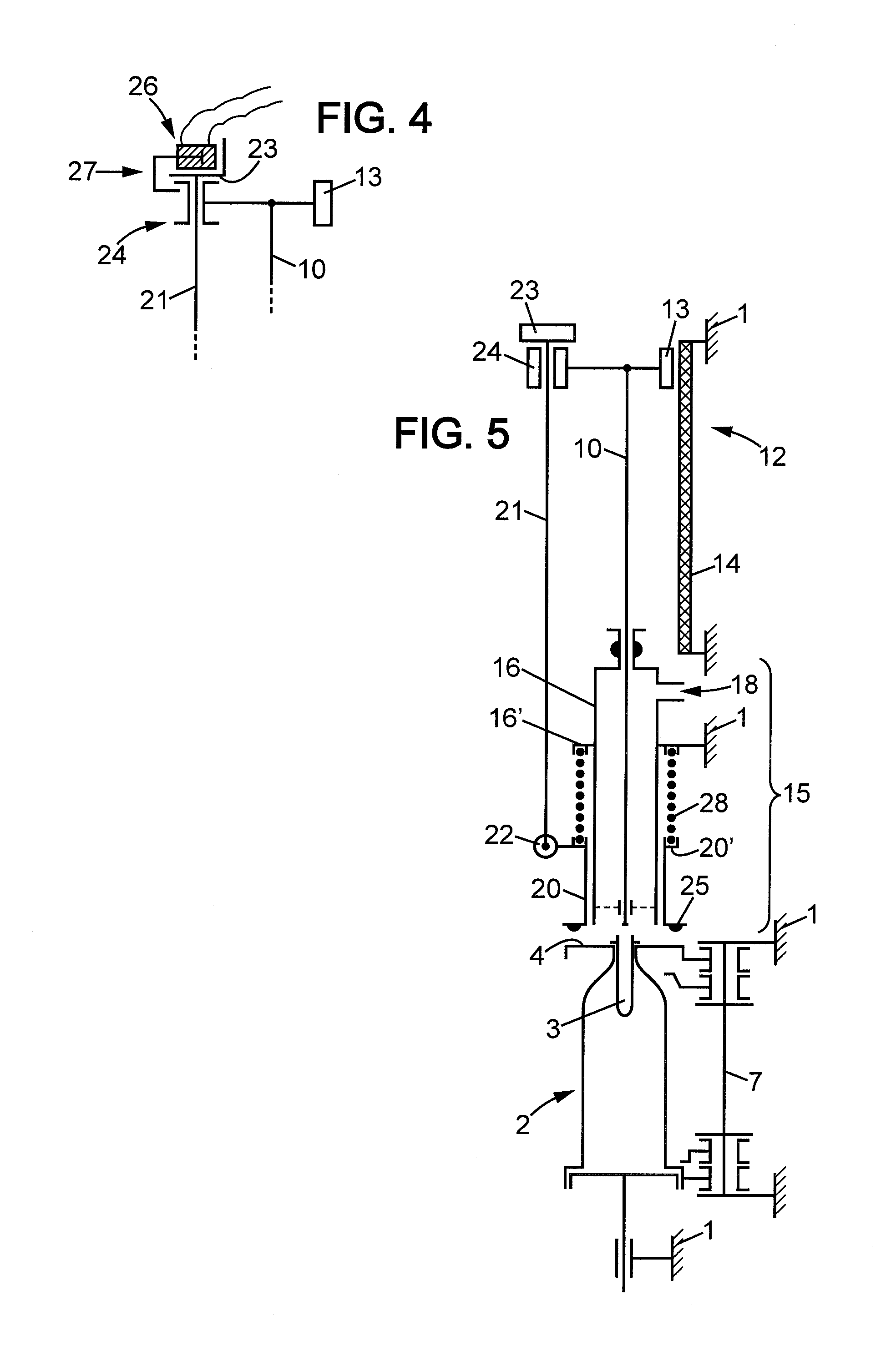
[0046]FIG. 1 illustrates, schematically, a mould carrier unit of the type which may be found on the carousel of an installation for the manufacture of containers, bottles or the like, by a stretch blow-moulding operation of preforms made of thermoplastic material, PET or the like.

[0047]This mould carrier unit comprises a general support structure 1 which is attached to the carousel, not shown. The actual mould 2 which receives a preform 3 is located on this support structure. This mould 2 may be of the jack-knife type, as shown schematically, consisting conventionally of two half-shells and a base; the control device disclosed below may also be suitable for all types of moulds.

[0048]The preform 3 rests on the inlet surface 4 of the mould 2. This mould 2 comprises two parts which are articulated by means of bearings 5 and 6 on an axis 7 which is attached to the support structure 1 of the mould carrier unit and it also comprises a base 8 which is vertically mobile, guided in a slide 9...


PUM

PropertyMeasurementUnit
pressureaaaaaaaaaa
lengthaaaaaaaaaa
depthaaaaaaaaaa

Abstract

The mould carrier unit for manufacturing containers by a stretch blow-moulding operation of preforms (3) arranged in moulds (2), comprises:on the one hand, a stretching rod (10) borne by a slide (13) which is mobile between an inactive position and an active position where its free end reaches the bottom of said mould (2),on the other hand, a nozzle (15) comprising a fixed body (16) extended by a bell (20), which is mobile under the action of appropriate means for passing from an inactive position where its free edge (25) is held substantially at the same level as the free end (11) of the stretching rod (10) to an active position where it is sealingly applied against the inlet surface (4) of the mould (2), to close the circuit of the blowing fluid,and said bell (20) comprises a bar (21) provided with a stop (23), which stop (23) cooperates with a support (24) formed on said slide (13) to permit said bell (20) to pass from its active position to the inactive position with the same law of motion as said stretching rod (10).

Description

FIELD OF THE INVENTION[0001]The present invention relates to a mould carrier unit arranged in an installation for stretch blow-moulding preforms in order to obtain containers of the bottle type or the like, made of thermoplastic material. The invention relates, more particularly, to the control of the blowing nozzle in addition to the method which is used for carrying out this control.DESCRIPTION OF THE PRIOR ART[0002]In a mould carrier unit, the blowing nozzle consists of a fixed part which is attached to the support structure of said mould carrier unit, and a mobile part which is in the shape of a ring or bell, the role thereof being to close, at the correct moment, the circuit for transmitting high pressure fluid which is intended for the mould and, in particular, for the preform to be blow-moulded.[0003]The control of the nozzle consists more specifically in displacing said bell between, on the one hand, an inactive position in which it is sufficiently remote from the mould to a...

Claims


Application Information

Patent Timeline
Patent Type & Authority Applications(United States)
IPC IPC(8): B29C47/92B29C48/92
CPCB29C49/12B29C49/58B29C2049/1257B29C47/92B29C2049/5817B29C2049/5875B29C2049/129B29C48/92B29C2948/92571B29C2948/92904B29C49/1222B29C49/123B29C2049/5862B29C2049/5893B29C49/122B29C49/1202
Inventor EUDIER, FABIENROUSSEAUDANEL, LAURENTLECOMTE, FREDERIC
Owner SIDEL PARTICIPATIONS SAS
Why Eureka
Try Eureka