

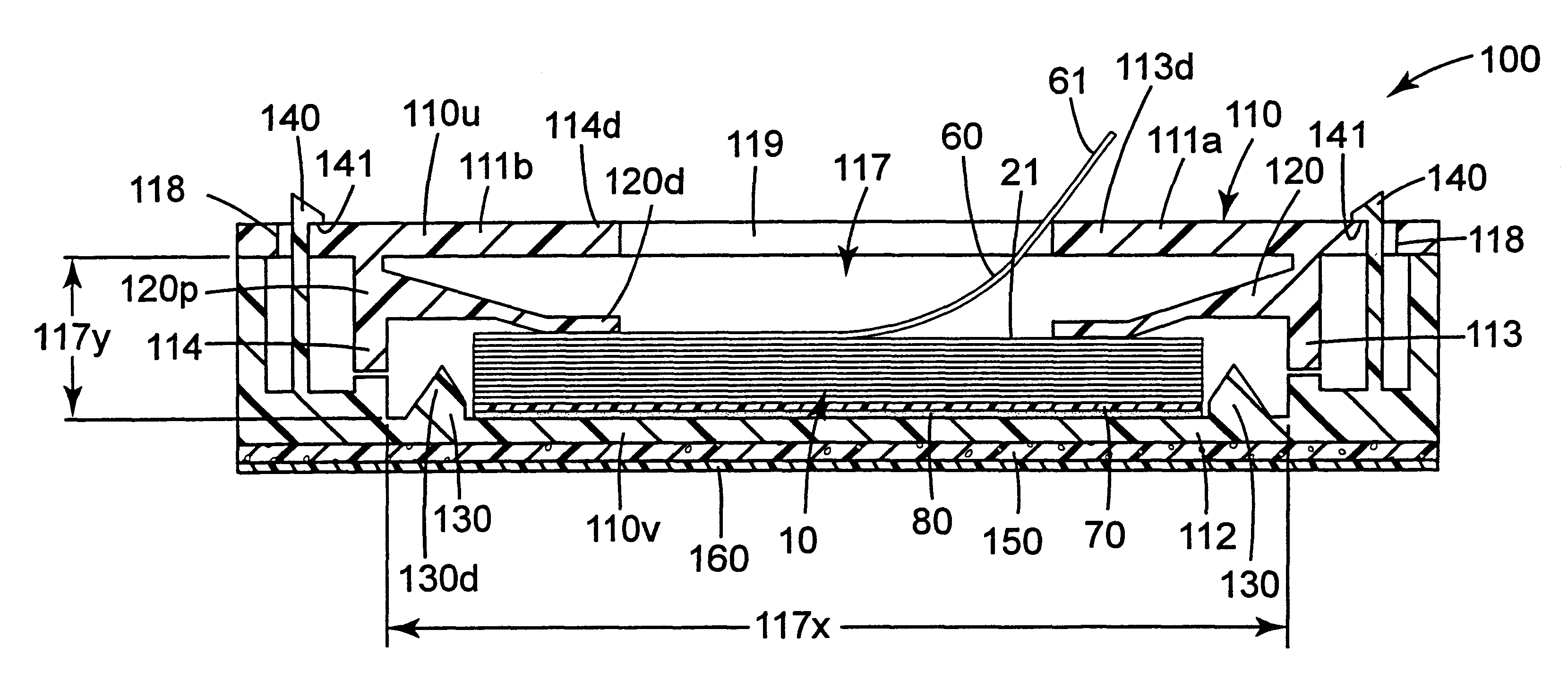
Tape strip pads and dispenser and method of dispensing individual tape strips
- Summary
- Abstract
- Description
- Claims
- Application Information
AI Technical Summary
Benefits of technology
Problems solved by technology
Method used
Image

Examples
first embodiment
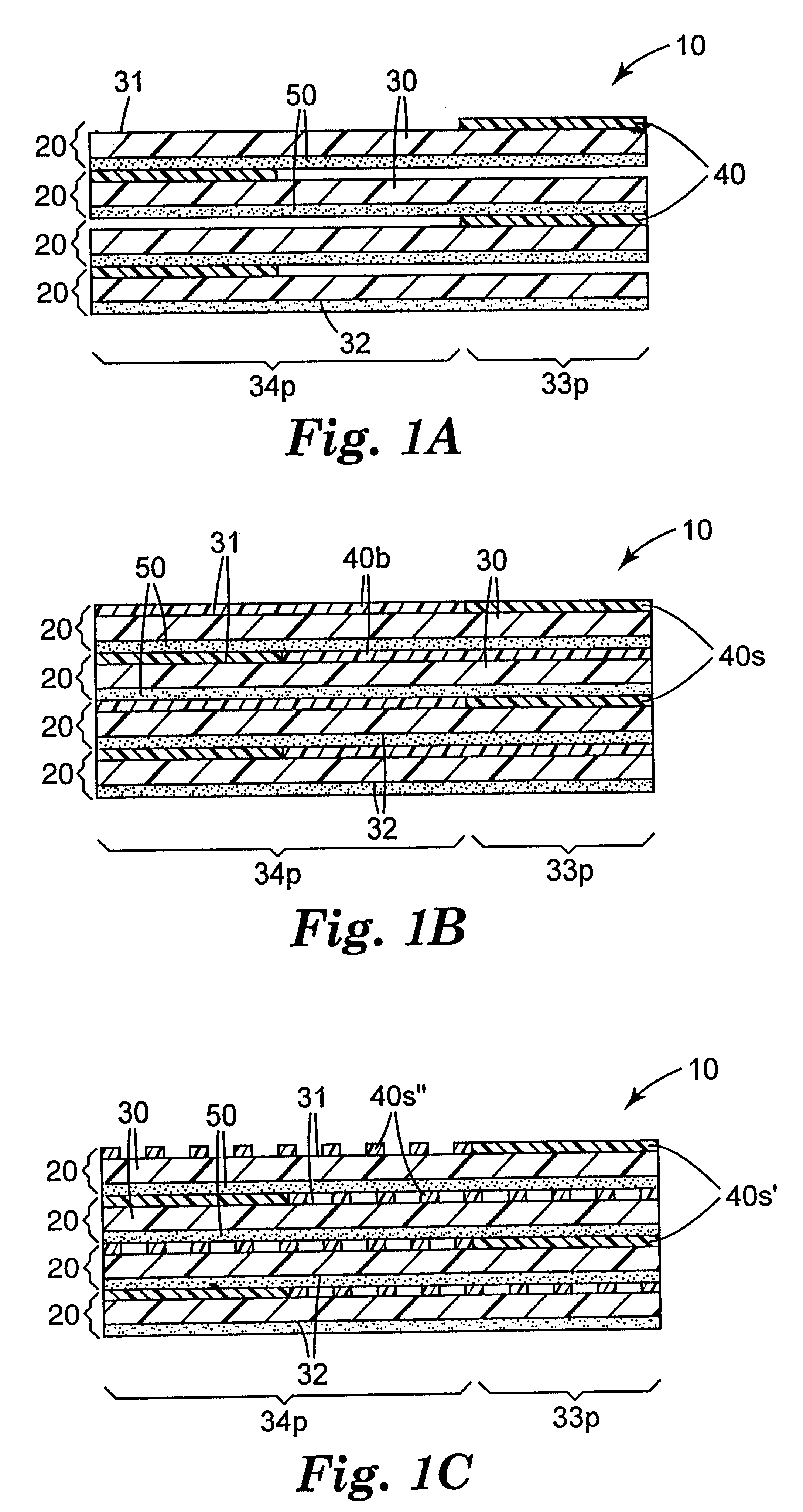
a differential release tape strip pad 10 according to the present invention is shown in FIG. 1A. The individual tape strips 20 include a coating of a LAB over only a first end portion 33p of the first major surface 31 of the substrate 30 and a coating of a pressure sensitive adhesive 50 over the entire second major surface 32 of the substrate 30. The tape strips 20 are stacked with the LAB coated first end portion 33p of successive strips 20 disposed at opposite longitudinal ends of the pad 10 to form a W-stacked pad 10 of adhesive tape strips 20. The substrate 30, LAB 40 and adhesive 50 should be selected and coated so as to provide a first (higher) adhesive level between the adhesive 50 of a first tape strip 20 and the substrate 30 of a second tape strip 20, and a second (lower) adhesive level between the adhesive 50 of the first tape strip 20 and the LAB coating 50 of the second tape strip 20.
second embodiment
A second embodiment of a differential release tape strip pad 10 according to the present invention is shown in FIG. 1B. The individual tape strips 20, shown in FIG. 2A, include a coating of a superior release LAB 40s over a first end portion 33p of the first major surface 31 of the substrate 30, a coating of a basic LAB 40b over a second end portion 34p of the first major surface 31 of the substrate 30, and a coating of a pressure sensitive adhesive 50 over the entire second major surface 32 of the substrate 30. The tape strips 20 are stacked with the superior release LAB coated first end portion 33p of successive strips 20 disposed at opposite longitudinal ends of the pad 10 to form a W-stacked pad 10 of adhesive tape strips 20. The superior release LAB 40s, basic LAB 40b and adhesive 50 are selected and coated to provide a first (higher) adhesive level between the adhesive 50 of a first tape strip 20 and the basic LAB 40b of a second tape strip 20, and a second (lower) adhesive le...
third embodiment
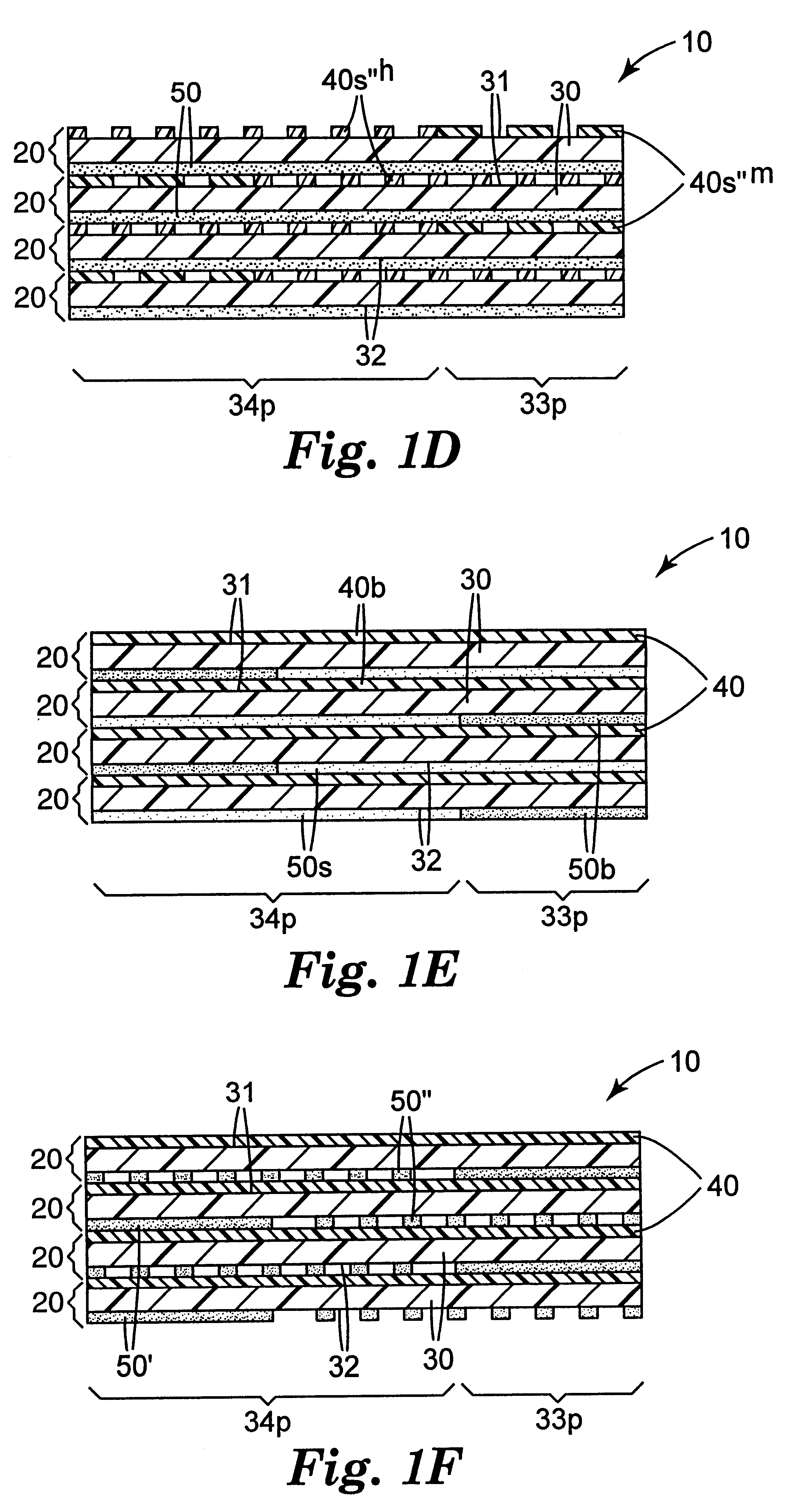
a differential release tape strip pad 10 according to the present invention is shown in FIG. 1C. The individual tape strips 20 include a continuous coating of a superior release LAB 40s' over a first end portion 33p of the first major surface 31 of the substrate 30, a discontinuous coating of the superior release LAB 40s" over a second end portion 34p of the first major surface 31 of the substrate 30 so as to form a pattern coating of the superior release LAB 40s", and a coating of a pressure sensitive adhesive 50 over the entire second major surface 32 of the substrate 30. The tape strips 20 are stacked with the continuously coated first end portion 33p of successive strips 20 disposed at opposite longitudinal ends of the pad 10 to form a W-stacked pad 10 of adhesive tape strips 20. The substrate 30, superior release LAB 40s, and adhesive 50 are selected and pattern coated to provide a first (higher) adhesive level between the adhesive 50 of a first tape strip 20 and the longitudin...
PUM
| Property | Measurement | Unit |
|---|---|---|
| Length | aaaaa | aaaaa |
| Length | aaaaa | aaaaa |
| Angle | aaaaa | aaaaa |
Abstract
Description
Claims
Application Information