Shock absorption structure for vehicle

Inactive Publication Date: 2010-10-07
HAYASHI GIJUTSU KENKYUSHO KK
View PDF14 Cites 22 Cited by
  • Summary
  • Abstract
  • Description
  • Claims
  • Application Information

AI Technical Summary

Benefits of technology

[0010]The present invention discloses a shock absorption structure to improve a shock absorbing performance i

Problems solved by technology

However, in the case that the occupant hits the interior member at multiple places when a shock occurs on th

Method used


Image

  • Shock absorption structure for vehicle
  • Shock absorption structure for vehicle
  • Shock absorption structure for vehicle

Examples


first embodiment

(1) First Embodiment

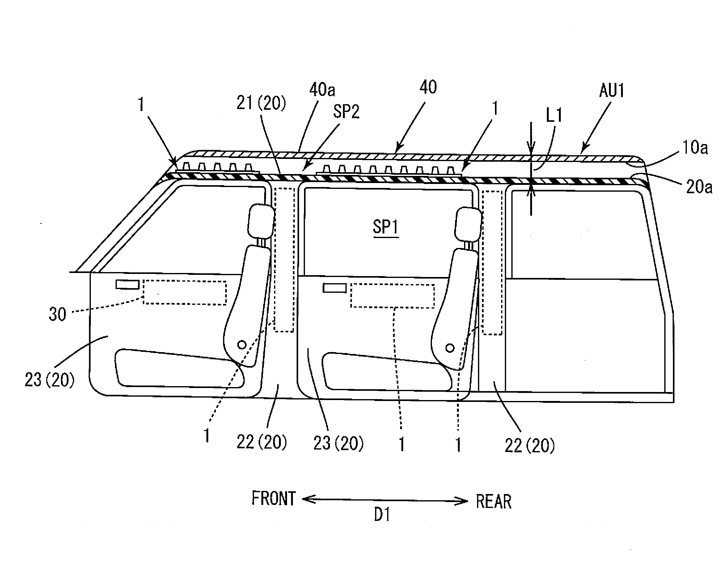
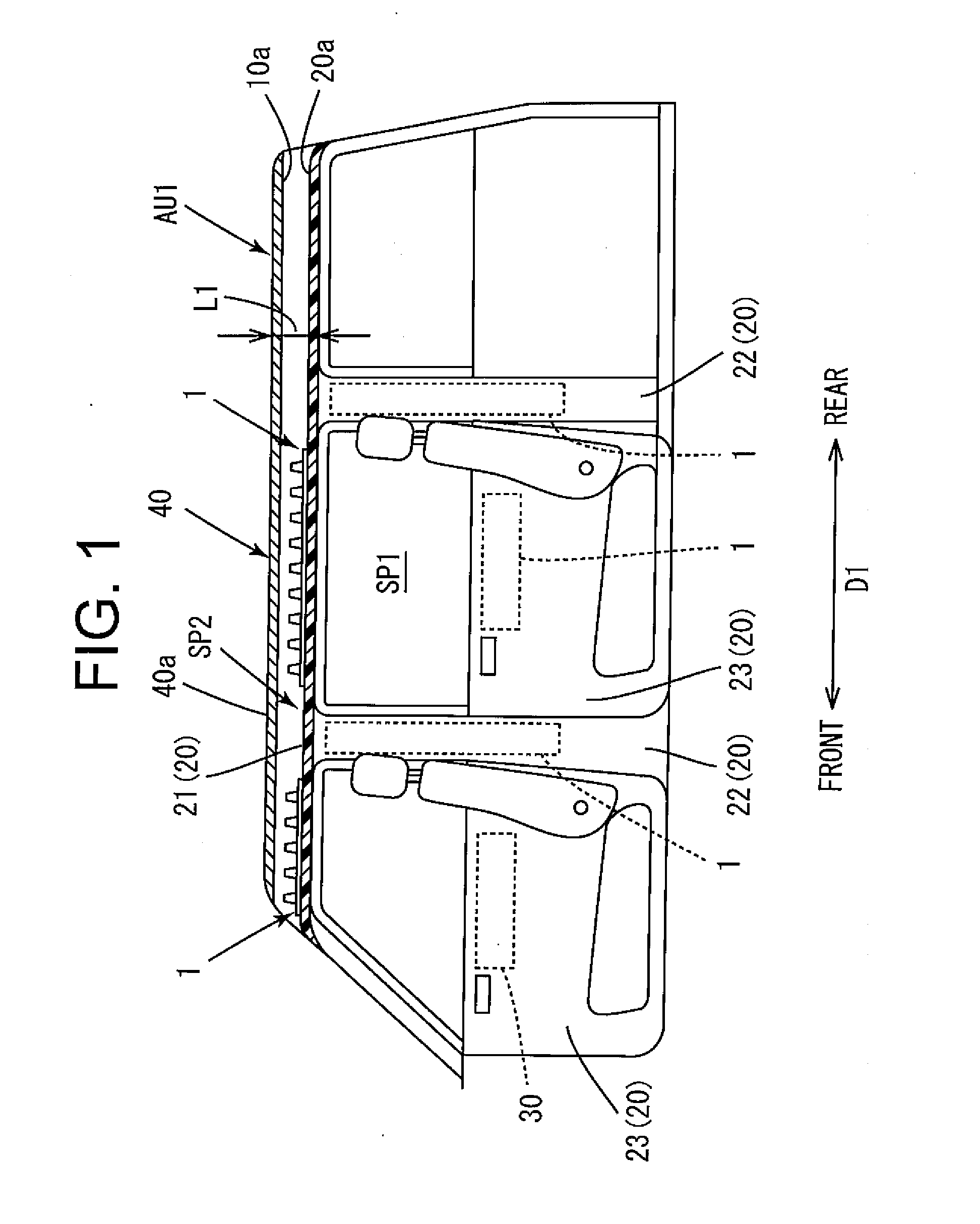
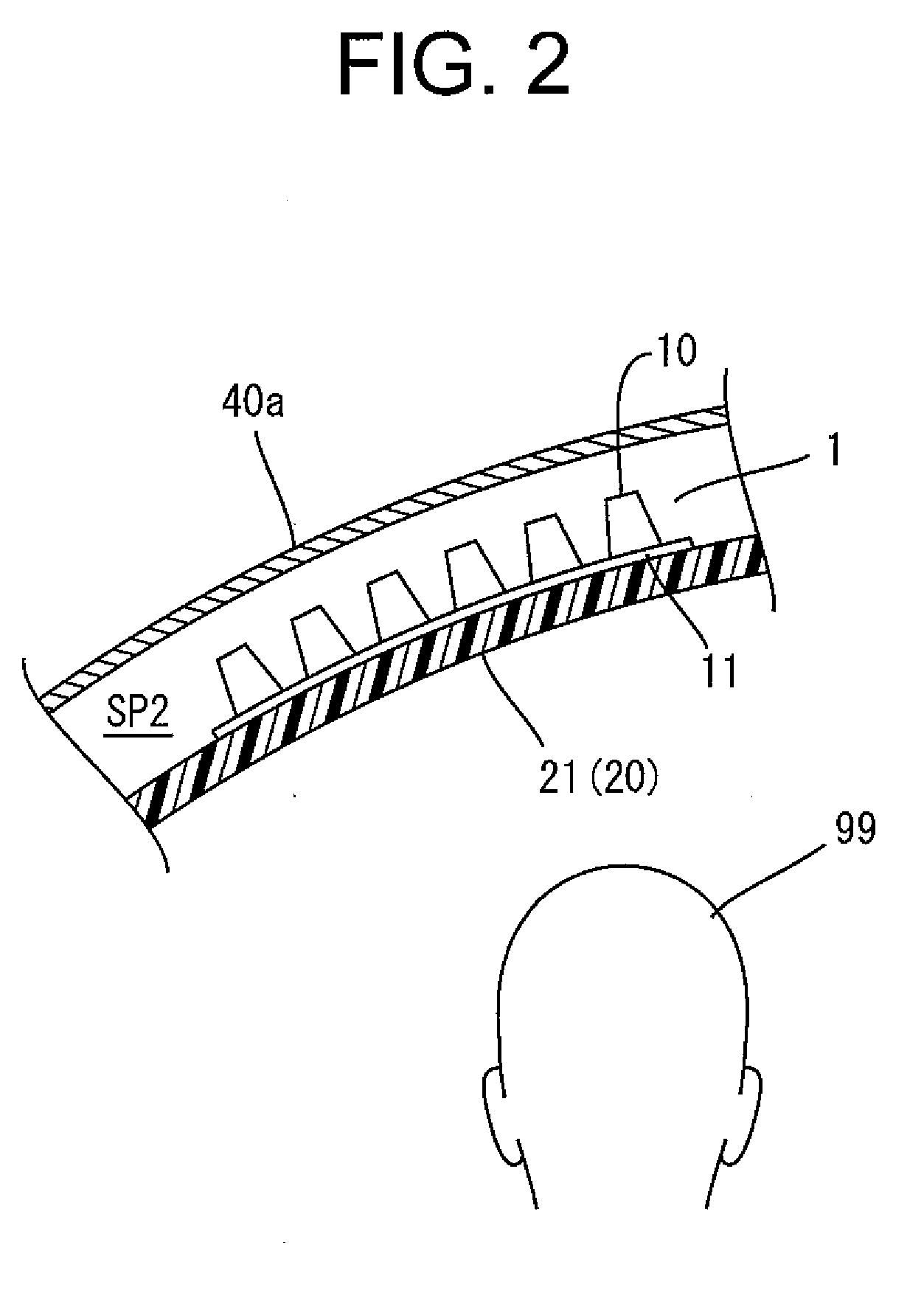
[0064]FIG. 1 is an exemplary illustration of a part cross-sectional view showing, in a vertical section parallel to a front-rear direction D1, a part of a road motor vehicle AU1 employing a shock absorption structure 1 for vehicle according to a first embodiment of the present invention. In the passenger motor vehicle AU1 shown in FIG. 1, a vehicle body is structured so that a vehicle body panel 40 is formed by bonding so as to enclose a passenger compartment SP1. In addition, various interior members 20 are installed on the passenger compartment side of the vehicle body panel 40. The shock absorption structure 1 is arranged, for example, in a space SP2 formed between the interior member 20 and the vehicle body panel 40, and mounted and fixed to a back surface 20a (surface toward outside of vehicle) of the interior member 20. The shock absorption structure 1 of the present embodiment is suitable for using in a place with a relatively limited space between the veh...

examples

[0097]The present invention will be specifically described below by showing examples of the first embodiment. However, the present invention is not limited by the examples.

[0098][Test Method]

[0099]According to the test method specified in Federal Motor Vehicle Safety Standard (FMVSS) 201 (U), the displacement s and the response load F of each of shock absorption structure samples were measured to obtain the load-displacement curve. Specifically, as shown in a schematic diagram in FIG. 7, a head of dummy with a mass of 4.54 kg that is called a free motion headform (FMH) was impacted at a speed of 24 km / h against a shock absorption structure sample 51 installed on a rigid body PL1 inclined at an elevation angle of 50°, and then the load-displacement curve was obtained.

[0100]The shock absorption structure sample 51 used in the test had a shape in which the shock absorbing parts 10 are arranged at even intervals in rows of 4×4 on the sheet-shaped base 11, and was integrally formed by in...

second embodiment

(2) Second Embodiment

[0130]FIG. 15 is an exemplary illustration of a perspective view showing an external appearance of a shock absorption structure 2 for vehicle according to a second embodiment; FIG. 16 is an exemplary illustration of a plan view of the shock absorption structure 2; FIG. 17 is a part cross-sectional view illustrating an example of a part of the motor vehicle in a vertical section parallel to the front-rear direction; and FIG. 18 is a part cross-sectional view illustrating the example of the part of the motor vehicle in a vertical section parallel to the vehicle width direction.

[0131]A plurality of shock absorbing parts of the shock absorption structure 2 include a plurality of first shock absorbing parts 110 and a plurality of second shock absorbing parts 120 having a height different from that of the first shock absorbing parts 110. In addition, the plurality of shock absorbing parts 110, 120 of the shock absorption structure 2 are structured by combining a first...


PUM


Abstract

The present invention discloses a shock absorption structure for vehicle installed between a vehicle body panel and an interior member that is closer to a passenger compartment side than the vehicle body panel. The shock absorption structure for vehicle includes a plurality of cup-shaped shock absorbing parts and a connecting part. Each of the shock absorbing parts has an open surface on a wide diameter side and a closed surface on a narrow diameter side, and also has a line-shaped induction part that is formed on a side face from an edge on the wide diameter side to a point midway toward an edge on the narrow diameter side and that induces a crack when a shock is applied. The connecting part connects the plurality of shock absorbing parts at the edges on the wide diameter sides.

Description

CROSS-REFERENCES TO RELATED APPLICATIONS[0001]This Application claims the benefit of priority and is a Continuation application of the prior International Patent Application No. PCT / JP2009 / 050736, with an international filing date of Jan. 20, 2009, which designated the United States, and is related to the Japanese Patent Application No. 2009-007248, filed Jan. 16, 2009 and the Japanese Patent Application No. 2008-010429, filed Jan. 21, 2008, the entire disclosures of all applications are expressly incorporated by reference in their entirety herein.BACKGROUND OF THE INVENTION[0002]1. Field of the Invention[0003]The present invention relates to a shock absorption structure for vehicle installed between a vehicle body panel and an interior member that is closer to a passenger compartment side than the vehicle body panel.[0004]2. Description of Related Art[0005]An interior member is installed on a passenger compartment side of a vehicle body panel composing a body of a motor vehicle. A ...

Claims


Application Information

Patent Timeline
IPC IPC(8): B60R21/04
CPCB60R13/0225B60R21/04F16F7/12B60R2021/0414B60R2021/0442B60R2013/0287
Inventor OHMIYA, HIROYUKITANIGUCHI, TAKAHIKO
Owner HAYASHI GIJUTSU KENKYUSHO KK
Why Eureka
Try Eureka