Magnetic coupling lens driving actuator

Active Publication Date: 2010-10-07
OLYMPUS CORP
View PDF2 Cites 8 Cited by
  • Summary
  • Abstract
  • Description
  • Claims
  • Application Information

AI Technical Summary

Benefits of technology

[0011]The present invention has been made in view of the above discussion. It is an object of the present invention to enhance the durability of the shape memory alloy wire. This is achieved by reduc

Problems solved by technology

However, an actuator that can be installed in a rigid section provided at the end of the endoscope cannot provide the

Method used


Image

  • Magnetic coupling lens driving actuator
  • Magnetic coupling lens driving actuator
  • Magnetic coupling lens driving actuator

Examples


first embodiment

[0025

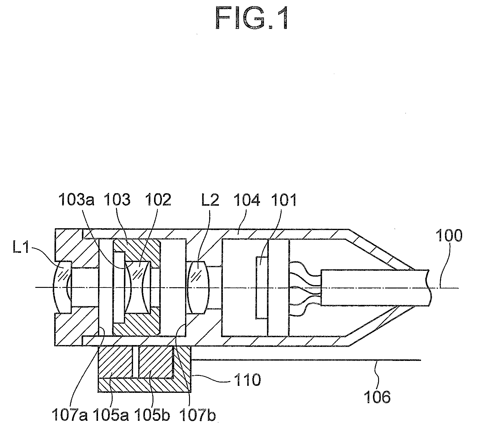
[0026]FIG. 1 is a cross-sectional view of a structure of a magnetic coupling lens driving actuator according to a first embodiment of the present invention.

[0027]In the magnetic coupling lens driving actuator according to the first embodiment, a lens holder 103 that holds a lens 102 (movable lens) is made of magnetic material (such as iron or stainless steel). The lens holder 103 is encased inside a lens tube 104. The lens holder 103 is arranged in such a manner that it can move in the direction of an optic axis 100 while securing an internal space 103a for holding the lens 102. Focusing and zooming is performed by moving the lens 102 along with the lens holder 103 in the direction of the optic axis 100. The incident light is converted into electrical signal in an imaging element 101.

[0028]On an outer surface of the lens tube 104 are provided two pieces of permanent magnets 105a and 105b (magnetic field producing members) in this order along the direction of the optic axis 100....

second embodiment

[0042

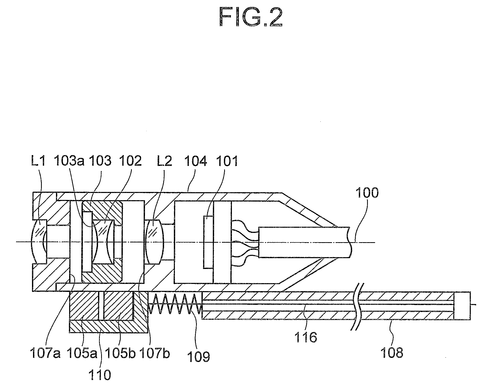
[0043]FIG. 2 is a cross-sectional view of a structure of a magnetic coupling lens driving actuator according to a second embodiment of the present invention. The structural elements in the second embodiment that are identical to those in the first embodiment have been assigned the same reference numeral s or reference symbols, as the case may be.

[0044]The magnetic coupling lens driving actuator according to the second embodiment includes a bendable tube 108 (tube member) that encases therewithin a shape memory alloy wire 116 (wire member). One end of the tube 108 is secured to the lens tube 104. The shape memory alloy wire 116 is passed through the lens tube 104 from its free end and comes out from the fixed end. The end of the shape memory alloy wire 116 that comes out from the fixed end of the tube 108 is attached to the permanent magnets 105a and 105b and the other end of the shape memory alloy wire 116 is connected to the fixed end of the tube 108.

[0045]A biasing spring 109...


PUM


Abstract

A magnetic coupling lens driving actuator includes an imaging element; a movable lens that is movable in a direction of an optic axis; a magnetic body that is coupled to the movable lens; a lens tube that encases and airtightly seals the imaging element, the movable lens, and the magnetic body; a magnetic field producing unit that is disposed on an outer surface of the lens tube and that is movable in the direction of the optic axis; and a wire member that has one end thereof attached to the magnetic field producing unit, and that is operative to move the magnetic field producing unit in the direction of the optic axis. The magnetic field producing unit includes two magnetic field producing members disposed with a predetermined gap therebetween in the direction of the optic axis, the magnetic body is disposed opposed to the predetermined gap within the lens tube, and the movable lens is moved by any one of deformation and movement of the wire member.

Description

CROSS-REFERENCE TO RELATED APPLICATIONS[0001]The present application is based upon and claims the benefit of priority from the prior Japanese Patent Application No. 2009-091860 filed on Apr. 6, 2009; the entire contents of which are incorporated herein by reference.BACKGROUND OF THE INVENTION[0002]1. Field of the Invention[0003]The present invention relates to a magnetic coupling lens driving actuator.[0004]2. Description of the Related Art[0005]Conventionally, to bring in full play the focusing and zooming functions of an optical system in an endoscope, it was necessary to provide a mechanism to move a lens within the lens tube of the endoscope in the direction of an optic axis. An actuator is generally used to move the lens within the lens tube. The amount of displacement achievable with a typical actuator depends on the length of the actuator. To achieve a longer displacement, a longer actuator is required. However, an actuator that can be installed in a rigid section provided at...

Claims


Application Information

Patent Timeline
IPC IPC(8): G02B7/04
CPCG02B23/2438G02B7/102
Inventor MATSUKI, KAORU
Owner OLYMPUS CORP
Why Eureka
Try Eureka