Cleaner head

a cleaner head and cleaning head technology, applied in the field of cleaner heads, can solve the problems of affecting the sideways movement of the cleaner head over the carpeted floor surface, and achieve the effects of improving pick up performance, improving air flow, and increasing the pressure within the cleaner head

Inactive Publication Date: 2010-10-14
DYSON TECH LTD
View PDF19 Cites 20 Cited by
  • Summary
  • Abstract
  • Description
  • Claims
  • Application Information

AI Technical Summary

Benefits of technology

[0014]The sole plate is preferably moveable relative to the housing. For example, a flexible annular seal may be located between the sole plate and the housing for allowing relative movement between the housing and the sole plate. When an air flow is generated through the suction opening, the pressure difference between the air passing through the cleaner head and the external environment causes the housing of the cleaner head to be sucked down towards the floor surface, whereas the fibres of a carpeted surface are lifted towards the housing of the cleaner head. Due to the presence of the flexible annular seal, which may be in the form of a flexible skirt or membrane, between the housing and the sole plate, the housing is capable of moving relative to the sole plate. Consequently, only a relatively small amount of force, if any, is applied to the sole plate by the housing, thereby preventing the sole plate from being pushed into the pile of the carpet by the housing. In turn, this means that the sole plate does not cause significant resistance to the movement of the cleaner head over the floor surface, and does not unduly restrict the flow of air into the cleaner head.
[0015]The engagement between the support members and the floor surface can restrict the movement of the housing towards the sole plate, thereby preventing the housing from being forced against the sole plate, particularly when the amount of suction provided at the suction opening is relatively high and/or when the pile of a carpeted floor surface is relatively deep.
[0016]The flexible annular seal preferably extends about the suction opening to provide an air-tight seal between the sole plate and the housing. The flexible annular seal may thus define part of a suction passage for conducting the dirt-bearing air from the suction opening to an air outlet. Thus, in comparison to a cleaner head using air channels to restrict the force acting on the cleaner head by allowing air to enter the suction passage from the external environment, the use of a flexible annular seal can enable an improved air flow into the cleaner head from around the periphery thereof and through a carpeted flow surface therebeneath to be achieved for a given air pressure within the housing of the cleaner head, thereby improving pick up performance.
[0017]The majority of the air flow entering the suction opening of the sole plate will pass beneath the ed

Problems solved by technology

However, the location of the wheels between fibres of the carpet can impa

Method used


Image

  • Cleaner head
  • Cleaner head
  • Cleaner head

Examples


Embodiment Construction

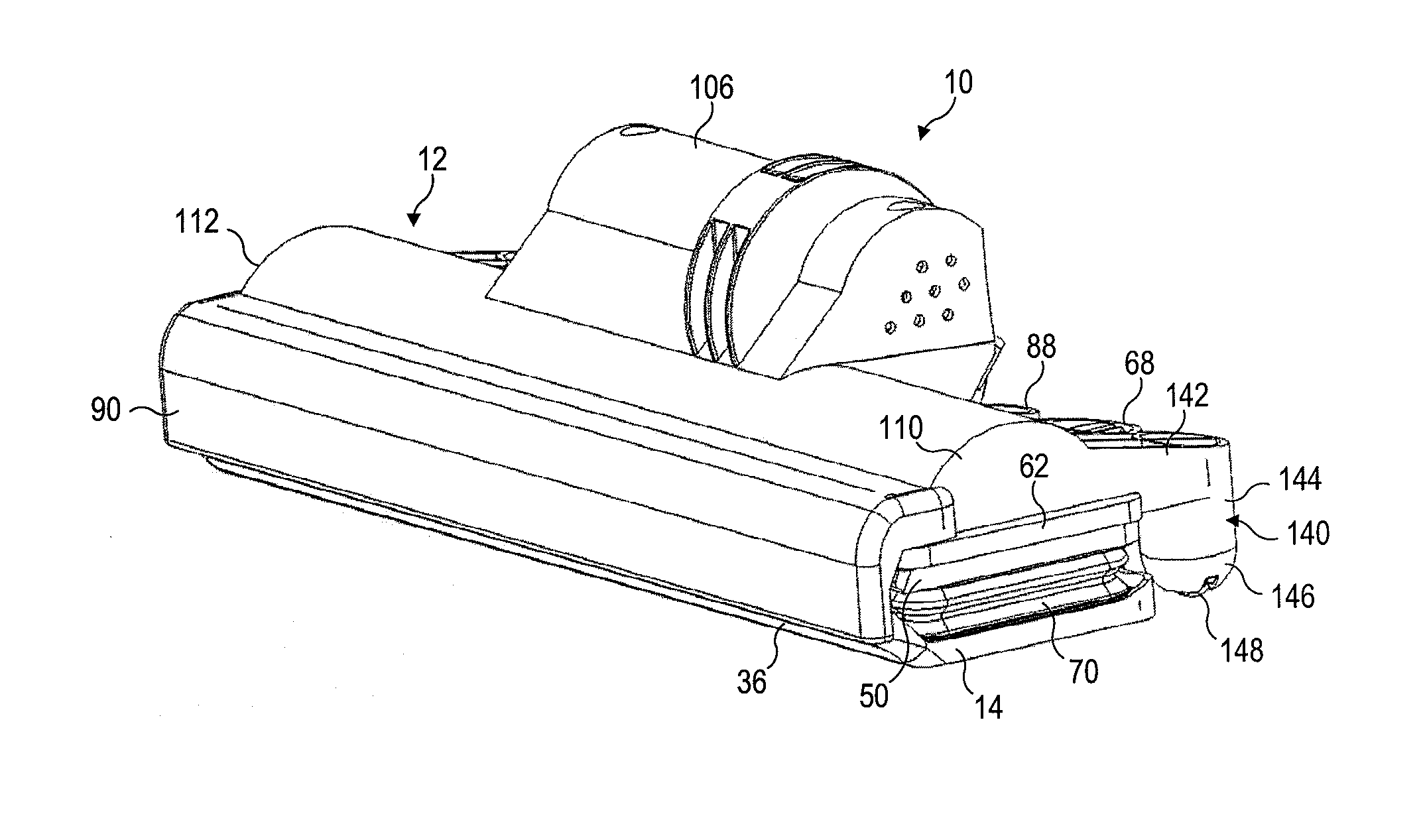
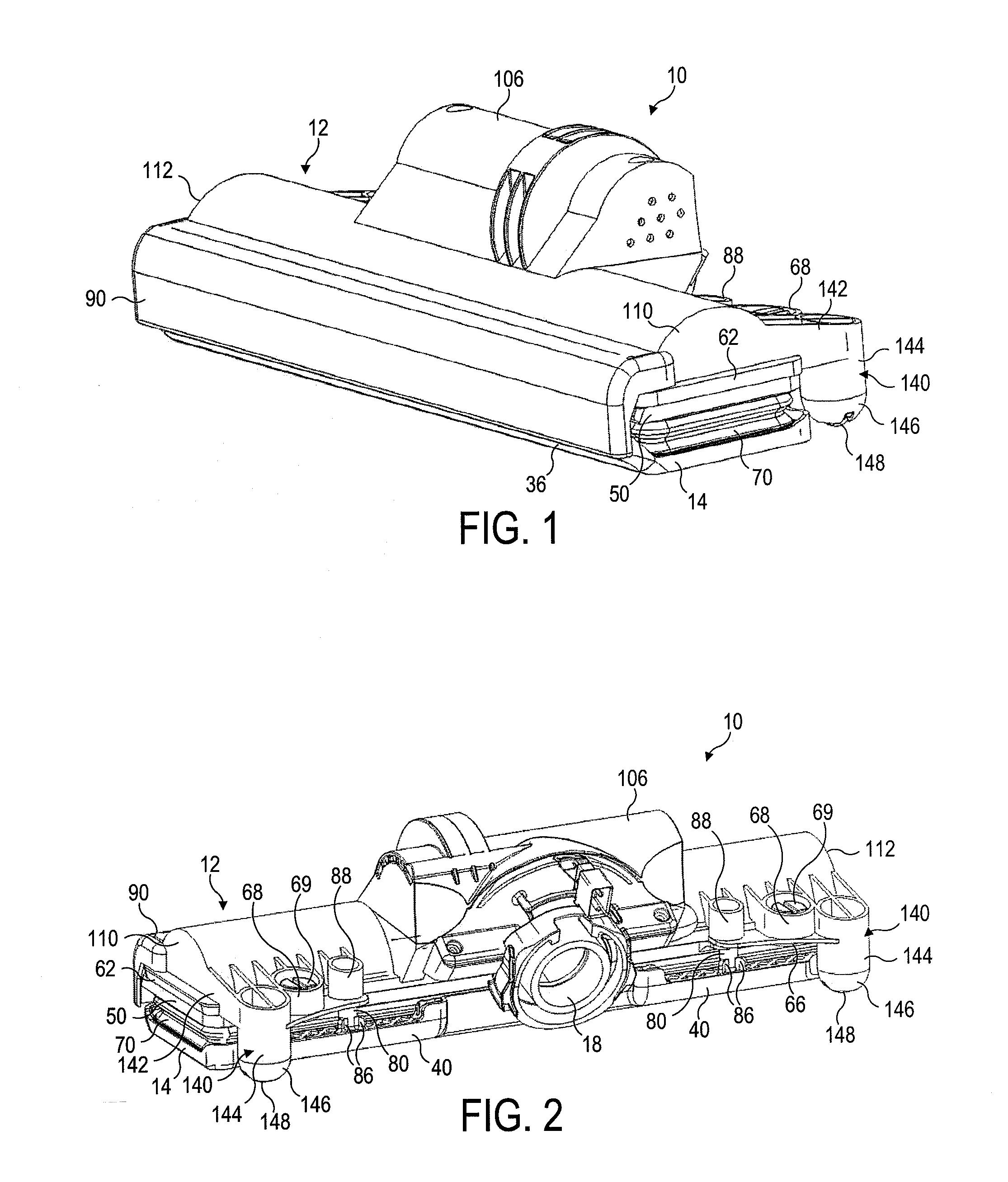
[0042]With reference first to FIGS. 1 and 2, a cleaner head 10 for a vacuum cleaner comprises a housing 12 and a lower plate, or sole plate 14, comprising a suction opening 16 through which a dirt-bearing fluid flow enters the cleaner head 10. The housing 12 defines a suction passage 17 (indicated in FIG. 7) extending from the suction opening 16 to a fluid outlet 18 located at the rear of the housing 12. The fluid outlet 18 is dimensioned to connect to a main body or a hose of an upright vacuum cleaner.

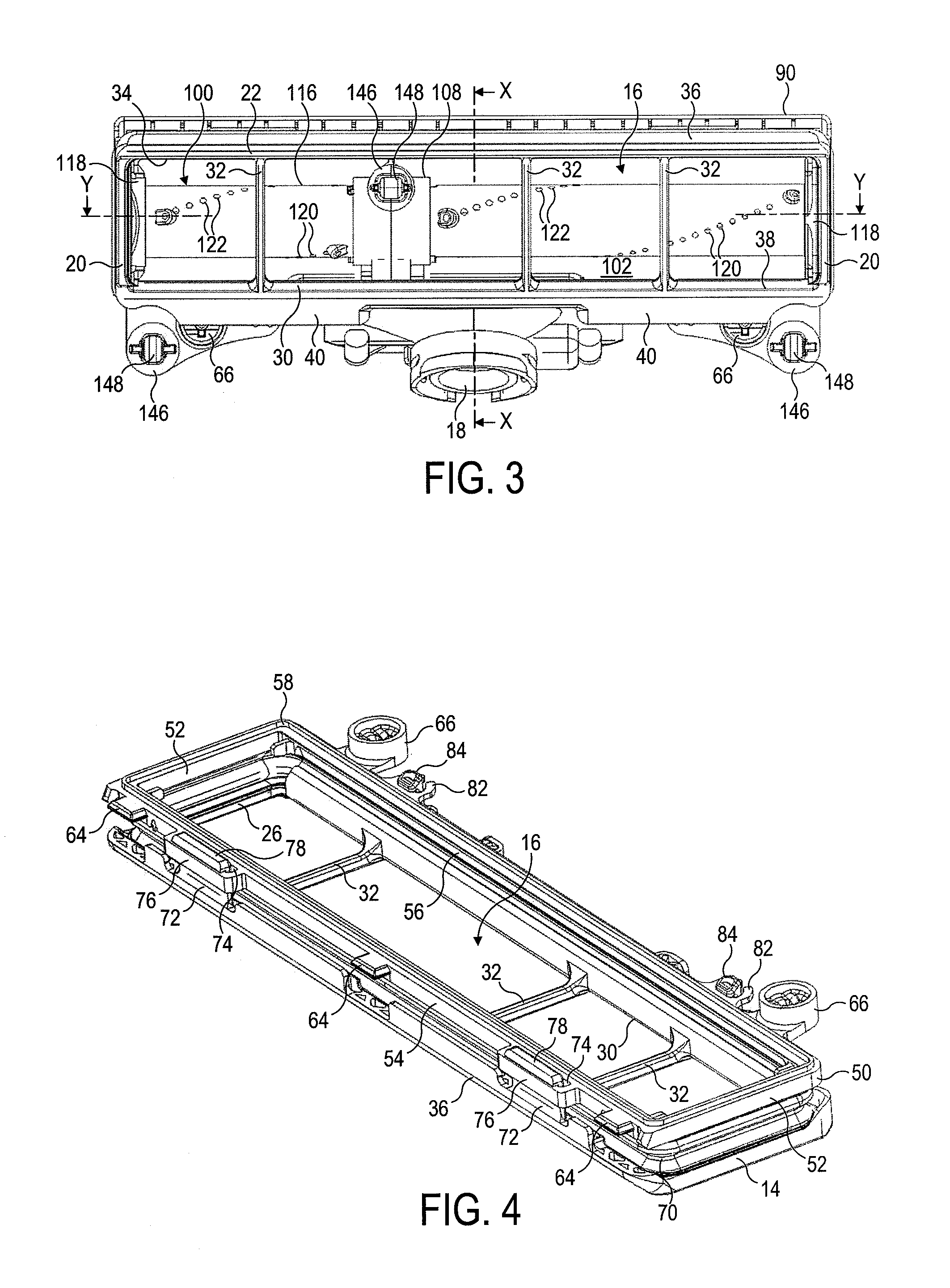
[0043]The sole plate 14 is illustrated in more detail in FIGS. 3 to 5. The sole plate 14 comprises a bottom surface which, in use, faces the floor surface to be cleaned and, as described in more detail below, engages the surface of a carpeted floor surface. The bottom surface of the sole plate 14 is generally planar, and comprises two opposing side sections 20, a leading section 22 and a trailing section 24 which extend about the suction opening 16.

[0044]The suction opening 16 is gene...


PUM


Abstract

A cleaner head for a cleaning appliance includes a housing, a suction opening through which dirt-bearing air enters the cleaner head, and a plurality of floor engaging support members connected to the housing. Each support member includes a curved lower surface and a rolling element located within a recessed portion of the lower surface of the support member. The outer surface of the rolling element is substantially coincident with a locus, or virtual surface, described by the lower surface of the support member.

Description

REFERENCE TO RELATED APPLICATIONS[0001]This application claims the priority of United Kingdom Application No. 0906362.9, filed Apr. 14, 2009, the entire contents of which are incorporated herein by reference.FIELD OF THE INVENTION[0002]The present invention relates to a cleaner head for a cleaning appliance. In its preferred embodiment, the present invention relates to a cleaner head for a vacuum cleaning appliance.BACKGROUND OF THE INVENTION[0003]An upright vacuum cleaner typically comprises a main body containing dirt and dust separating apparatus, a cleaner head mounted on the main body and having a suction opening, and a motor-driven fan unit for drawing dirt-bearing air through the suction opening. The dirt-bearing air is conveyed to the separating apparatus so that dirt and dust can be separated from the air before the air is expelled to the atmosphere.[0004]The suction opening is directed downwardly to face the floor surface to be cleaned. The separating apparatus can take th...

Claims


Application Information

Patent Timeline
IPC IPC(8): A47L9/02
CPCA47L9/06
Inventor MAGUIRE, SCOTT ANDREWBOWER, ANDREW JAMES
Owner DYSON TECH LTD
Why Eureka
Try Eureka