
Method and apparatus for suppressing cavitation on the surface of a streamlined body

Inactive Publication Date: 2010-10-14
BERGER VLADIMIR +1
View PDF9 Cites 11 Cited by
  • Summary
  • Abstract
  • Description
  • Claims
  • Application Information

AI Technical Summary

Benefits of technology

[0015]It is an object of the present invention to provide a device and method for preventing cavitation on the trailing part that is a downstream part of the streamlined body in a flow of liquid. It is still a further object to provide a method of preventing cavitation that is versatile and that applies to various constructions such as propellers, hydrofoils, impellers, etc. It is another object to provide a method and device for suppressing cavitation without the use of such complicated methods as optimization of streamlined profiles or other geometrical changes of the object. A further object is to reduce resistance of a streamlined body to a flow of liquid under conditions of development of turbulence by preventing development of cavitation in the flow-separation area.
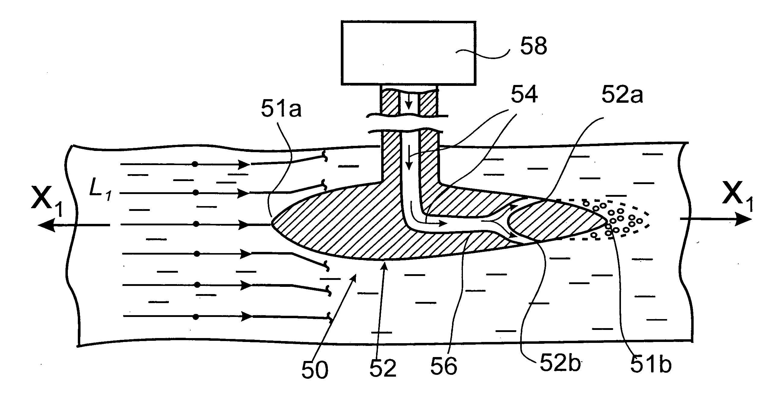
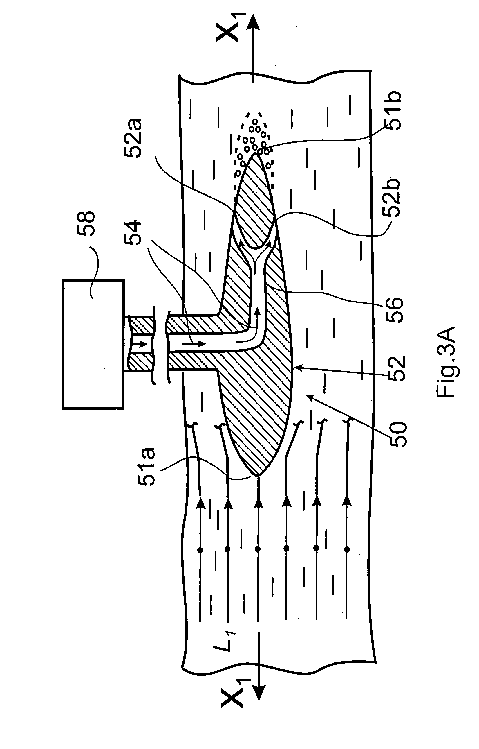
[0017]Provision of the aforementioned gaseous flow protects the surface of the streamlined body from interaction with the separated flow. The viscous friction that normally occurs between the surface of a streamlined body and a liquid ceases to exist. As a result, a boundary layer that normally exists on the surface of the streamlined body on the line of separation of the flow is replaced by the artificially created gas layer. This excludes development of turbulence when the velocity of flow reaches a critical value. Suppression of turbulence, in turn, results in suppression of cavitation and decreases resistance to movement of the body in a liquid.

Problems solved by technology

In all embodiments, the flow of gas creates a continuous gaseous layer between the liquid and the surface on the trailing side of the streamlined body, which is at risk of cavitation-based deterioration.

Method used


Image

  • Method and apparatus for suppressing cavitation on the surface of a streamlined body
  • Method and apparatus for suppressing cavitation on the surface of a streamlined body
  • Method and apparatus for suppressing cavitation on the surface of a streamlined body

Examples


Embodiment Construction

[0028]In the context of the present description, the term “a streamlined body in a flow of liquid” covers a condition wherein a relative movement exists between the liquid and the streamlined body, i.e., a stationary streamlined body may be located into a flow of a moving liquid, a streamlined body may move in a stationary liquid, or both the body and the liquid may participate in movements relative to each other.

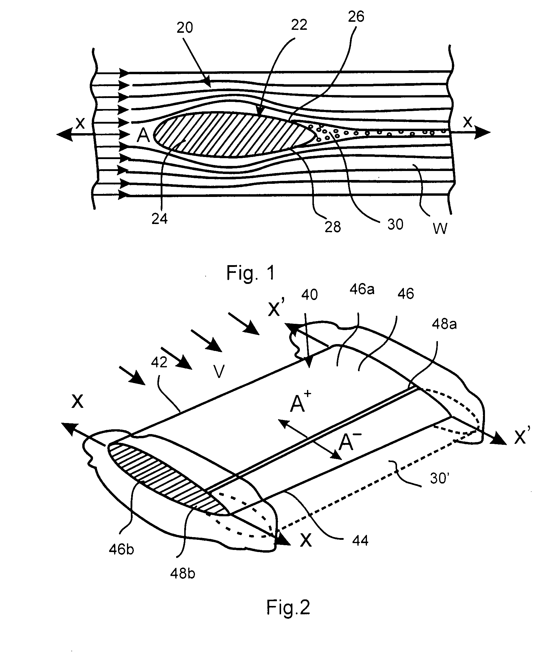
[0029]A three-dimensional view of a part of a conventional hydrofoil 40 of a vessel (not shown) moving in a liquid under conditions illustrated in FIG. 1 is shown in FIG. 2. In this drawing, reference numeral 42 designates the leading edge of the hydrofoil 40, and reference numeral 44 designates the trailing edge of the hydrofoil 40. The leading edge 42 and the trailing edge 44 are connected by the streamlined surface 46, which defines the streamlined profile of the hydrofoil 40 from above and below and which consists of a leading part 21 that confronts the flow of liquid a...


PUM


Abstract

A method and a device for suppression of cavitation and thus for reducing resistance to movement of a streamlined body in a flow of liquid based on the principle that development of cavitation bubbles in the area of separation of the flow that is accompanied by the development of turbulence is prevented by injecting a gaseous medium into the aforementioned area for separating the flow of liquid from the surface of the streamlined body. The device of the invention can be realized in the form of various specific embodiments with supply of gas under pressure to the cavitation-development area through a plurality of perforations and transverse slits.

Description

FIELD OF INVENTION [0001]The present invention relates to the field of hydrodynamics, in particular to suppressing cavitation on the surfaces of streamlined bodies operating in liquid media under conditions that may cause turbulence. In particular, the invention relates to hydraulic machines and devices such as hydraulic pumps, turbines, propellers, rudders, valves, or the like, the working elements of which may be subject to cavitations.BACKGROUND OF THE INVENTION [0002]In order to better understand the principle of the present invention and to become familiar with the terminology, let us consider a relative movement between a streamlined body and a fluid, e.g., a liquid. In order to simplify the explanation, let us assume that the streamlined body having an oval longitudinal cross section is moving in a flow of liquid in the direction of the large axis of the oval cross section.[0003]Although the explanation relates specifically to a substantially oval-shaped cross section, it sho...

Claims


Application Information

Patent Timeline
IPC IPC(8): B63B1/24F15D1/10
CPCB63B1/38Y02T70/122F15D1/12Y10T137/0396Y10T137/218Y02T70/10
Inventor BERGER, VLADIMIRSAPRONOV, SERGEY
Owner BERGER VLADIMIR
Learn More