Insulated electric wire and method for producing insulated electric wire

a technology of insulated electric wire and electric wire, which is applied in the direction of insulating conductor/cable, insulating non-insulating conductor, cables, etc., can solve the problems of reducing the lifetime of insulated electric wire and by extension, the lifetime of electrical equipment, etc., and achieves low dielectric constant, insulating property, and solvent resistance. , the effect of suppressing the decrease in the strength of the insulating layer

Active Publication Date: 2019-11-05
SUMITOMO ELECTRIC IND LTD +1
View PDF12 Cites 0 Cited by
  • Summary
  • Abstract
  • Description
  • Claims
  • Application Information

AI Technical Summary

Benefits of technology

[0014]An insulated electric wire and a method for producing an insulated electric wire according to the present invention can suppress a decrease in the strength, insulating property, and solvent resistance of an insulating layer while realizing a low dielectric constant.

Problems solved by technology

The generation of corona discharge may cause, for example, a local increase in the temperature, generation of ozone, and generation of ions, which may result in dielectric breakdown at an early stage and result in a decrease in the lifetime of the insulated electric wire, and by extension, the lifetime of the electrical equipment.

Method used


Image

  • Insulated electric wire and method for producing insulated electric wire
  • Insulated electric wire and method for producing insulated electric wire

Examples


first embodiment

Insulated

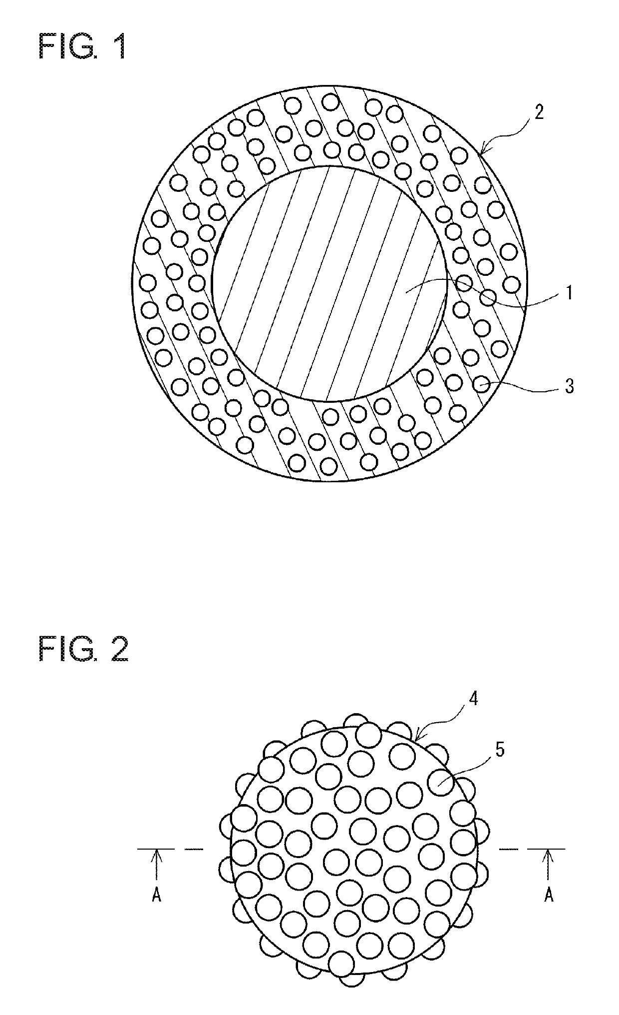
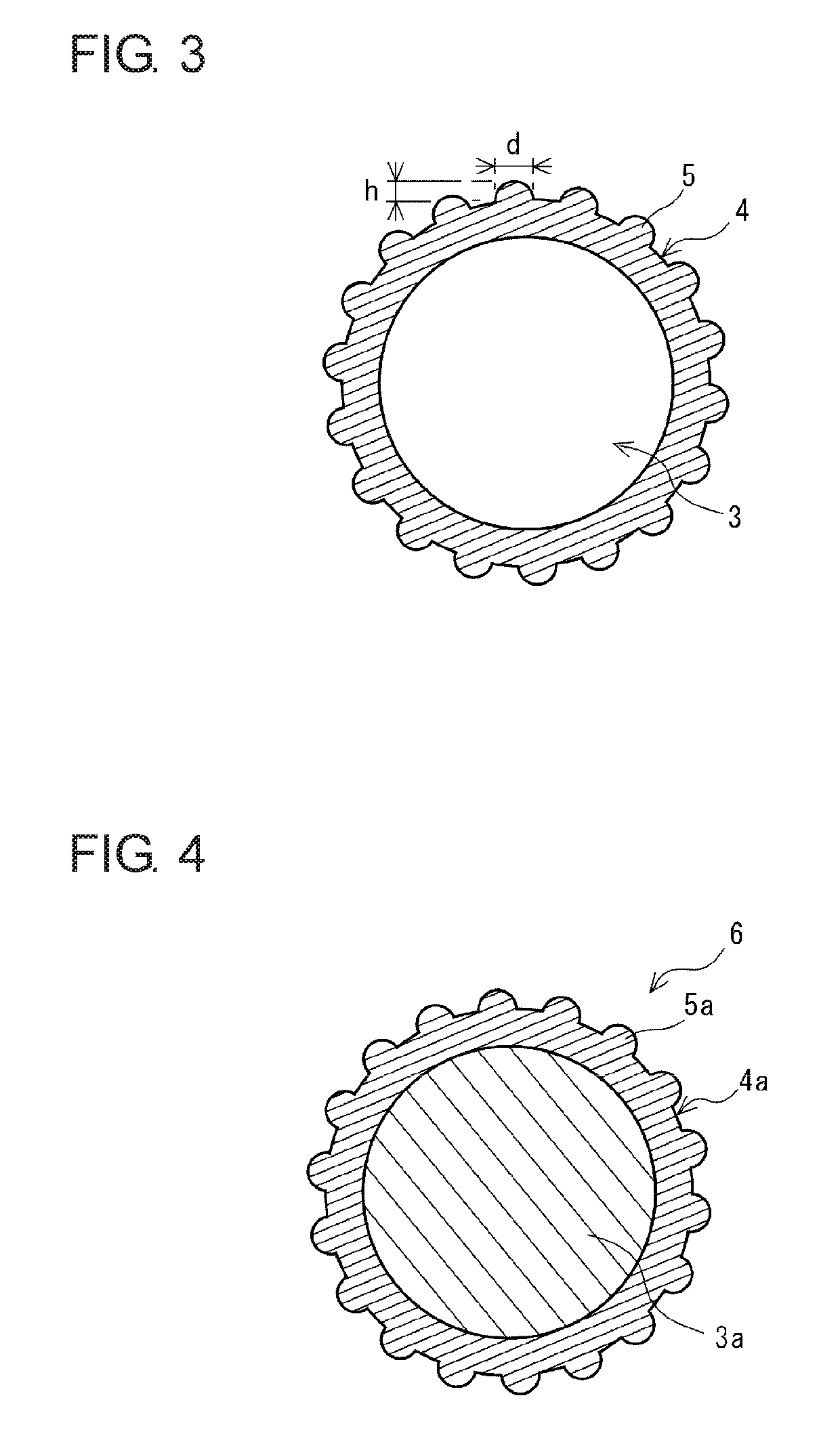
[0023]An insulated electric wire in FIG. 1 includes a linear conductor 1 and a single insulating layer 2 formed on the outer peripheral surface of the conductor 1. The insulating layer 2 has a plurality of pores 3. As illustrated in FIGS. 2 and 3, the insulated electric wire includes an outer shell 4 on the periphery of each of the pores 3, and the outer shell 4 has a plurality of projections 5 on the outer surface thereof.

[0024]Since the insulated electric wire, includes the insulating layer 2 having the plurality of pores 3, a low dielectric constant can be realized. Since the insulating layer 2 of the insulated electric wire includes the outer shells 4 on the peripheries of the pores 3, the pores 3 are less likely to communicate with each other. As a result, the size of the pores 3 of the insulating layer 2 is unlikely to vary. Furthermore, in the insulated electric wire, since each of the outer shells 4 has the plurality of projections 5 on the outer surface thereof, th...

examples

[No. 1]

[0077]First, copper was cast, stretched, subjected to wire drawing, and softened to obtain a conductor having a circular section and an average diameter of 1 mm. A resin composition was prepared by diluting a main polymer with a solvent by using a polyimide precursor as the main polymer and N-methyl-2-pyrrolidone as the solvent. Core / shell composite particles including cores formed of PMMA particles and having a mean particle size of 3.0 μm and shells formed of a silicone were used as hollow-forming particles. The hollow-forming particles were then dispersed in the resin composition to prepare a resin varnish. The shells of the core / shell composite particles had a plurality of projections on the outer surfaces thereof. The average height of the projections was 0.1 μm, the average diameter at the bottom of the projections was 0.1 μm, and the average number of the projections present per unit area (14 μm2) of one shell was 90. The core / shell composite particles had a silicone c...


PUM

PropertyMeasurementUnit
heightaaaaaaaaaa
heightaaaaaaaaaa
thicknessaaaaaaaaaa

Abstract

An insulated electric wire includes a linear conductor and one or more of insulating layers formed on an outer peripheral surface of the conductor. In the insulated electric wire, at least one of the one or more of insulating layers has a plurality of pores, outer shells are disposed on peripheries of the pores, and each of the outer shells has a plurality of projections on an outer surface thereof.

Description

CROSS-REFERENCE TO RELATED APPLICATIONS[0001]This U.S. National stage application claims priority under 35 U.S.C. § 119(a) to Japanese Patent Application No. 2016-165189, filed in Japan on Aug. 25, 2016, the entire contents of which are hereby incorporated herein by reference.TECHNICAL FIELD[0002]The present invention relates to an insulated electric wire and a method for producing an insulated electric wire. The present invention claims priority from Japanese Patent Application No. 2016-165189 filed on Aug. 25, 2016, and the entire contents of the Japanese application are incorporated herein by reference.BACKGROUND ART[0003]In electrical equipment to which a high voltage is applied, for example, in a motor that is used at a high voltage, a high voltage is applied to an insulated electric wire included in the electrical equipment, and partial discharge (corona discharge) is easily generated on a surface of an insulating coating of the insulated electric wire. The generation of coron...

Claims


Application Information

Patent Timeline
Patent Type & Authority Patents(United States)
IPC IPC(8): H01B7/02H01B13/16H01F5/06H01B7/17H01B3/44H01B5/00
CPCH01B7/17H01B3/44H01B7/02H01B7/0233H01B5/004H01B13/16H01F5/06H01B3/306H01B3/46
Inventor OTA, SHINYAYAMAUCHI, MASAAKISUGAWARA, JUNTAMURA, YASUSHIYOSHIDA, KENGO
Owner SUMITOMO ELECTRIC IND LTD
Why Eureka
Try Eureka