Insulated electric wire and varnish for forming insulating layer

a technology of insulating layer and varnish, which is applied in the direction of insulating conductor/cable, insulating wire/cable,auxillary non-insulating conductor, etc., can solve the problems of reducing the lifetime of insulated electric wire and thus the lifetime of electrical equipment, and achieves the effect of reducing the dielectric constant, reducing the strength, and reducing the insulating property

Active Publication Date: 2020-11-10
SUMITOMO ELECTRIC IND LTD +1
View PDF12 Cites 0 Cited by
  • Summary
  • Abstract
  • Description
  • Claims
  • Application Information

AI Technical Summary

Benefits of technology

[0014]An insulated electric wire and a varnish for forming an insulating layer according to embodiments of the present invention can suppress a decrease in the strength, insulating property, and solvent resistance of an insulating layer while decreasing the dielectric constant.

Problems solved by technology

The generation of corona discharge may cause, for example, a local increase in the temperature, generation of ozone, and generation of ions, which may result in dielectric breakdown at an early stage and result in a decrease in the lifetime of the insulated electric wire and thus the lifetime of the electrical equipment.

Method used


Image

  • Insulated electric wire and varnish for forming insulating layer
  • Insulated electric wire and varnish for forming insulating layer
  • Insulated electric wire and varnish for forming insulating layer

Examples


first embodiment

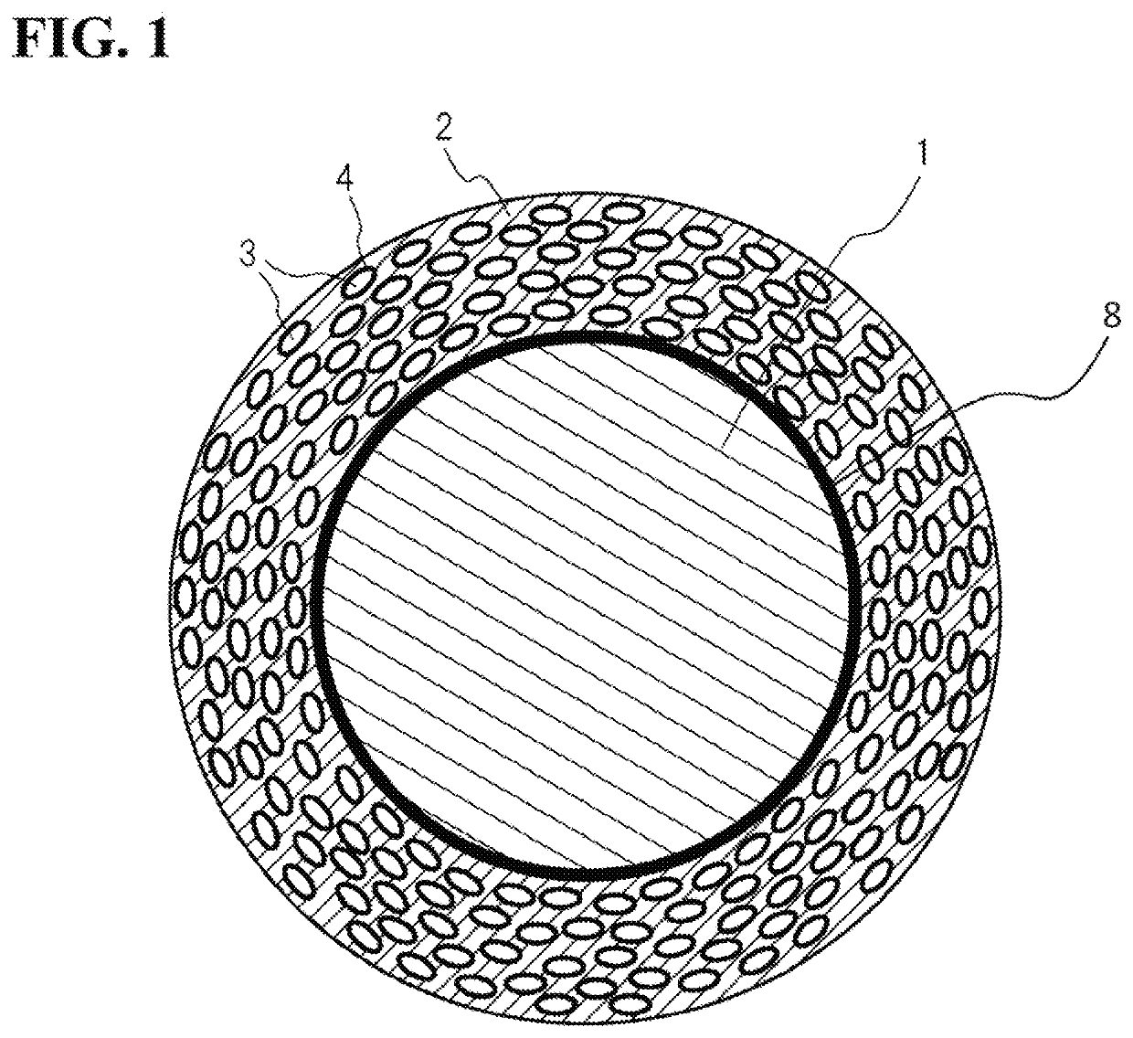
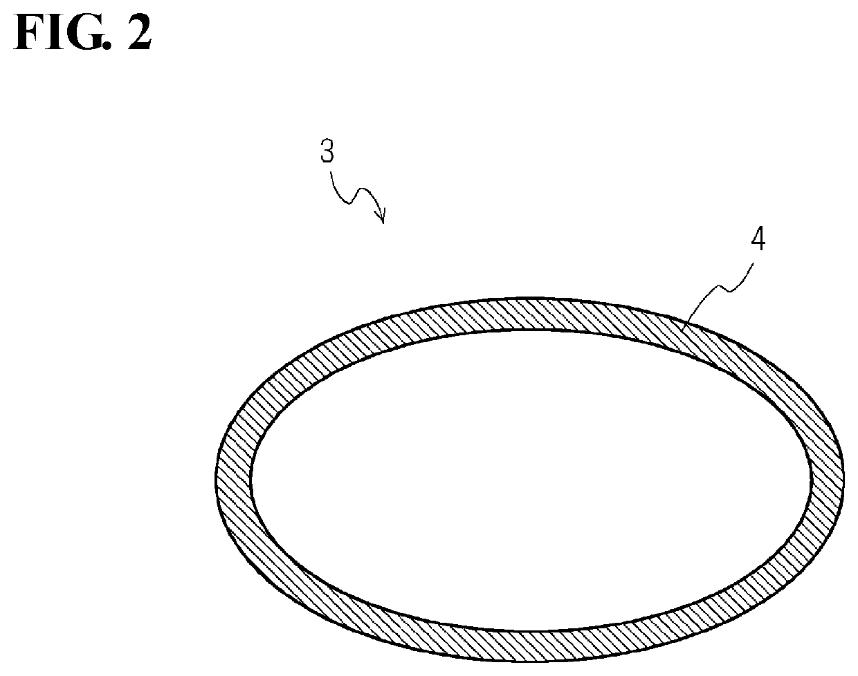
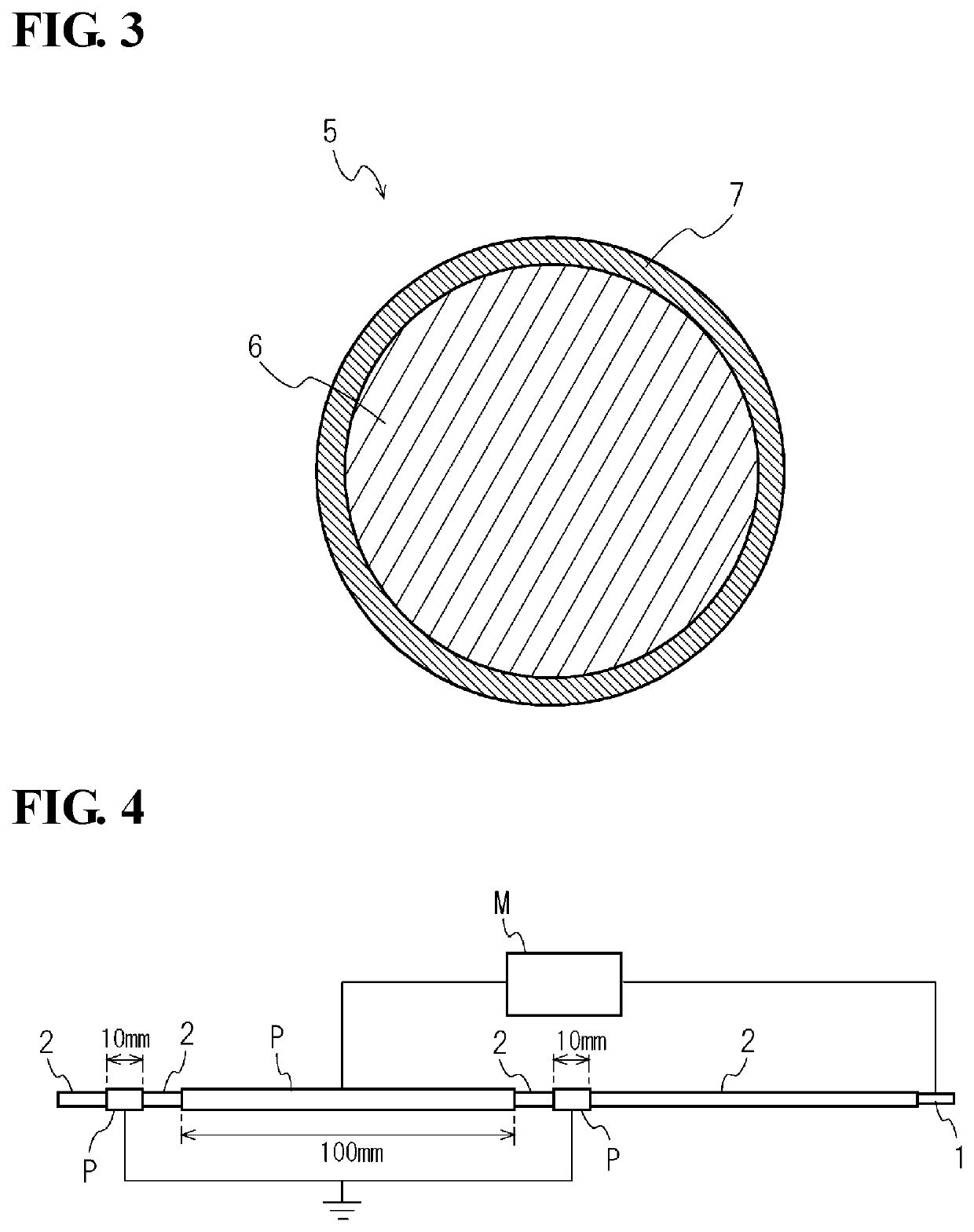
[0049]The varnish for forming an insulating layer is a varnish used for forming the insulating layer 2 of the insulated electric wire. The varnish for forming an insulating layer according to a first embodiment contains a resin composition forming a matrix, and hollow-forming particles 5 having a core-shell structure and dispersed in the resin composition. In the varnish, cores 6 of the hollow-forming particles 5 contain a thermally decomposable resin as a main component, and shells 7 of the hollow-forming particles 5 contain a main component having a higher thermal decomposition temperature than the thermally decomposable resin.

(Resin Composition)

[0050]The resin composition is a composition containing, for example, a main polymer, a diluting solvent, and a curing agent. The main polymer is not particularly limited. When a thermosetting resin is used, examples of the main polymer include polyvinylformal precursors, thermosetting polyurethane precursors, thermosetting acrylic resin p...

second embodiment

[0069]The varnish for forming an insulating layer according to a second embodiment is a varnish used for forming the insulating layer of the insulated electric wire as in the varnish for forming an insulating layer of the first embodiment. The varnish for forming an insulating layer of the second embodiment contains a resin composition forming a matrix, and hollow particles dispersed in the resin composition. In the varnish, outer shells of the hollow particles contain a resin as a main component.

[0070]The resin composition of the varnish for forming an insulating layer may be the same as that of the varnish for forming an insulating layer of the first embodiment.

[0071]Examples of the resin of the main component of the hollow particles include polystyrene, silicone, fluororesins, and polyimides. Among these resins, silicone is preferred from the viewpoint of imparting elasticity to the outer shells and easily improving an insulating property and heat resistance.

[0072]The lower limit...

example 1

[0092]The present invention will now be described in more detail by way of Examples. However, the present invention is not limited to these Examples.


PUM

PropertyMeasurementUnit
thicknessaaaaaaaaaa
thicknessaaaaaaaaaa
thicknessaaaaaaaaaa

Abstract

An insulated electric wire includes a linear conductor and one or a plurality of insulating layers formed on an outer peripheral surface of the conductor. At least one of the one or plurality of insulating layers contains a plurality of pores, outer shells are disposed on peripheries of the pores, and the outer shells are derived from shells of hollow-forming particles having a core-shell structure. A varnish for forming an insulating layer contains a resin composition forming a matrix and hollow-forming particles having a core-shell structure and dispersed in the resin composition. In the varnish, cores of the hollow-forming particles contain a thermally decomposable resin as a main component, and shells of the hollow-forming particles contain a main component having a higher thermal decomposition temperature than the thermally decomposable resin.

Description

CROSS-REFERENCE TO RELATED APPLICATIONS[0001]This U.S. National stage application claims priority under 35 U.S.C. § 119(a) to Japanese Patent Application No. 2015-212371 filed on Oct. 28, 2015, the entire contents of which are hereby incorporated herein by reference.TECHNICAL FIELD[0002]The present invention relates to an insulated electric wire and a varnish for forming an insulating layer.BACKGROUND ART[0003]In electrical equipment to which a high voltage is applied, for example, in a motor that is used at a high voltage, a high voltage is applied to an insulated electric wire included in the electrical equipment, and partial discharge (corona discharge) is easily generated on a surface of an insulating coating of the insulated electric wire. The generation of corona discharge may cause, for example, a local increase in the temperature, generation of ozone, and generation of ions, which may result in dielectric breakdown at an early stage and result in a decrease in the lifetime o...

Claims


Application Information

Patent Timeline
Patent Type & Authority Patents(United States)
IPC IPC(8): H01B3/48H01B3/44H01B3/00C08J9/26H01B13/06H01B3/46H01B7/02H01B13/16H01B5/00
CPCH01B3/447C08J9/26H01B3/46H01B7/0208H01B3/006H01B13/06H01B7/0233C08J2207/06C08J2201/046C08J2377/00H01B5/004C08J2433/12H01B13/16C08J2483/04C08J2379/08
Inventor OTA, SHINYAMAEDA, SHUHEISAITO, HIDEAKISUGAWARA, JUNYAMAUCHI, MASAAKITAMURA, YASUSHIYOSHIDA, KENGOFURUYA, YUDAIHATANAKA, YUJI
Owner SUMITOMO ELECTRIC IND LTD
Why Eureka
Try Eureka