
Plaster for tracheostoma valves

a tracheostoma valve and tracheal tube technology, applied in the field of tracheal tube and tracheal tube glue, can solve the problems of cumbersome cleaning with unhealthy solvents, difficult to have sufficient adherence on patients with large tracheostoma, and inability to fully contact the skin, etc., to achieve less cumbersome handling and cause any tension or discomfort to the patient

Active Publication Date: 2010-10-14
ATOS MEDICAL
View PDF24 Cites 41 Cited by
  • Summary
  • Abstract
  • Description
  • Claims
  • Application Information

AI Technical Summary

Benefits of technology

[0009]One object of the present invention is to provide a plaster of the kind referred to herein having attachment means that follows the depressed or lowered tracheostoma and the relatively plane surrounding skin for optimal adherence without causing any tension or discomfort to the patient. The attachment means should also be able to take up much larger forces and not come loose as easily as prior art products. Furthermore, the plaster should be less cumbersome to handle for the patient.
[0011]A further object of the present invention is to provide a plaster for connection to the tracheostoma which is of disposable type so that there is no need for the patient to perform the cumbersome and health jeopardising steps of changing the double-coated adhesive tape, which by many patients is felt as a major problem.
[0013]Another object is to make the plaster of biocompatible and environment friendly materials, reducing risks for both patient and environment.

Problems solved by technology

This type of plaster causes problems regarding tension and incomplete contact with the skin close to the tracheostoma due to the fact that the stoma normally is lowered or depressed.
The tape must not extend beyond the edge of the flange, as any exposed adhesive of the tape will attract dirt and dust discolouring the tape.
Though the products of the above type work well in many respects, there are still some problems.
The known products are normally of a type to be re-used, which means that cumbersome cleaning by means of unhealthy solvents has to be effected.
Often the patient is elderly and will find problems in performing these steps.
As the flange is relatively small and the adhesive tape does not extend beyond it or at least not far beyond it, it is difficult to have sufficient adherence on patients having a large and irregular tracheostoma.
The flange is inclined but since the tracheostoma often is lowered or depressed and the skin around the tracheostoma often is relatively plane the inclined flange will cause surrounding skin to adapt an unnatural form and in this way creates tensions in the tissues and thus flangeomfort to the patient.
Furthermore, there is an increased risk that the plaster will more easily loosen from the patient's neck.

Method used


Image

  • Plaster for tracheostoma valves
  • Plaster for tracheostoma valves
  • Plaster for tracheostoma valves

Examples


Embodiment Construction

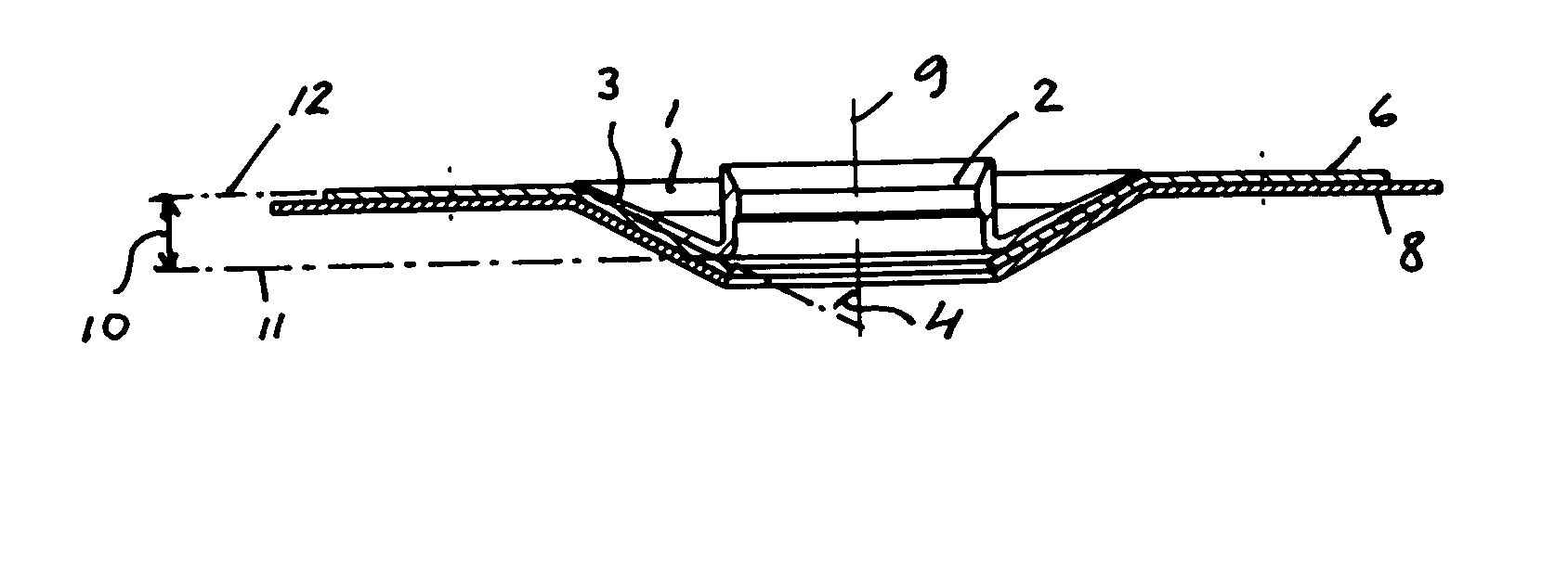
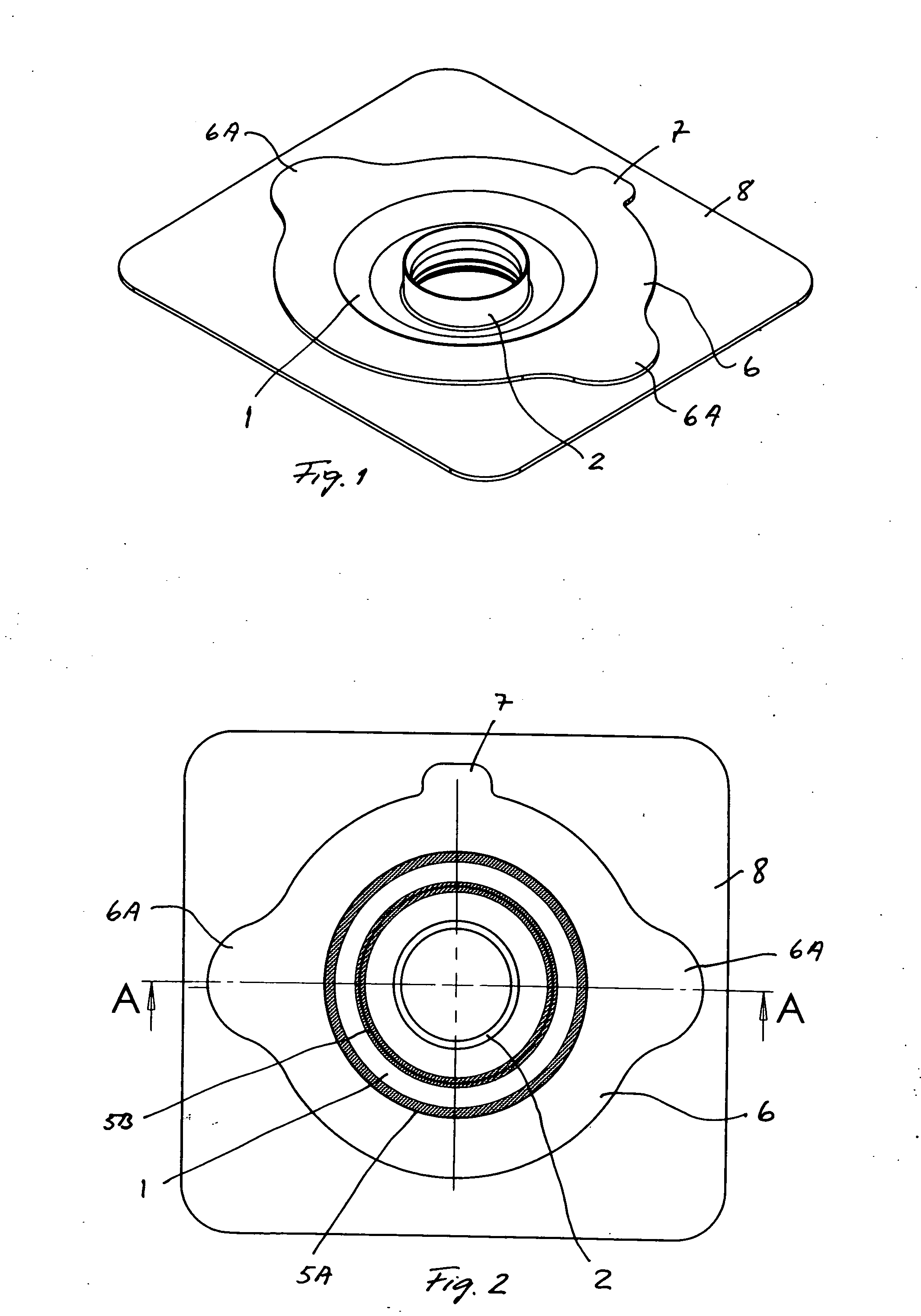
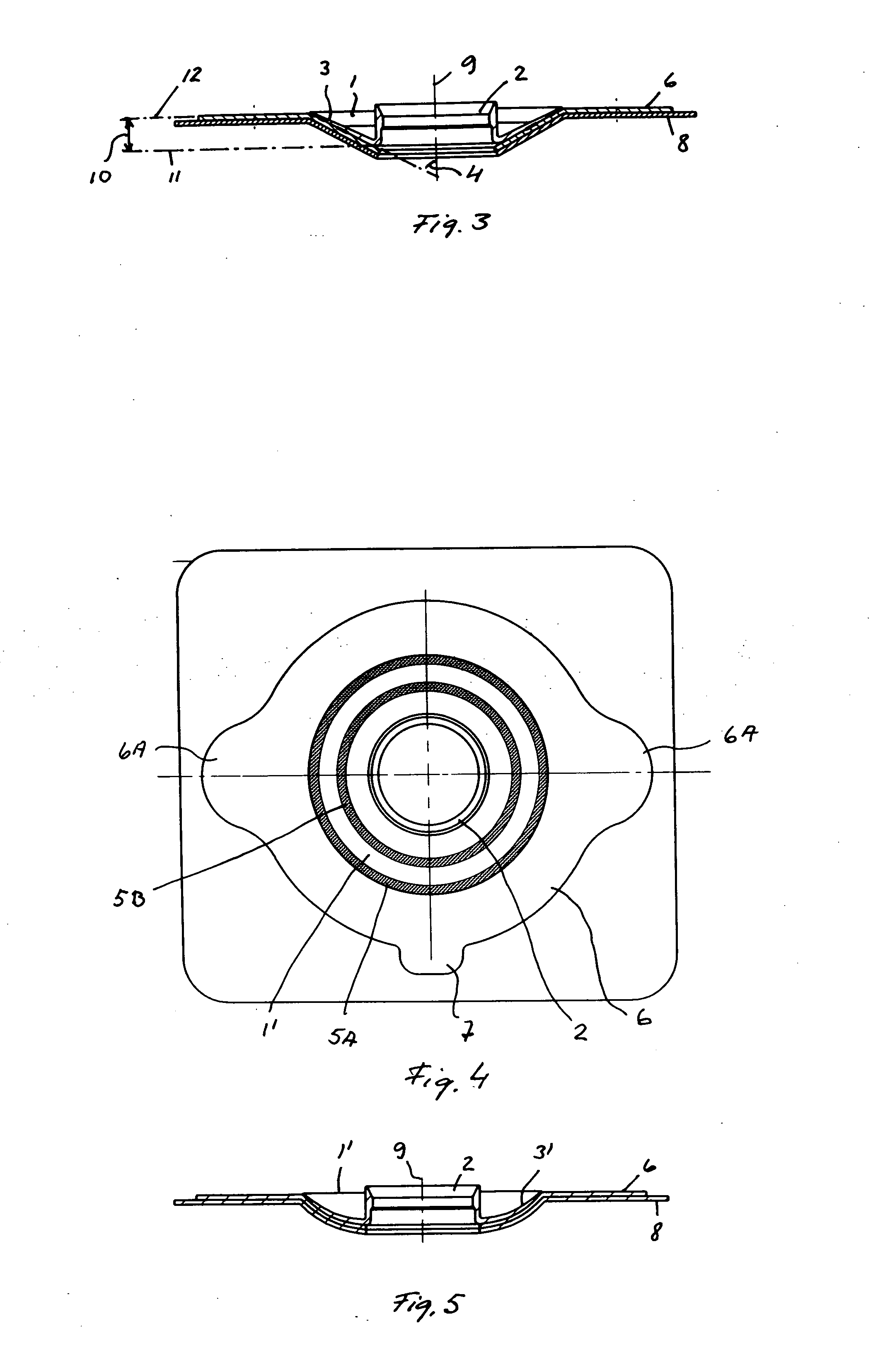
[0029]The plaster according to the present invention comprises a central, annular flange 1, which forms a central socket 2 and a flange 3 concentrically surrounding socket 2. Thus, socket 2 forms a central opening of flange 1. In the embodiments of FIGS. 1 to 4 flange 3 is inclined at an angle 4 in relation to the central axis 9 of socket 2. The angle 4 may vary but is preferably between 30° and 80° and more preferably between 50° and 70°. Due to the angle 4 of flange 3 a base plane 11 perpendicular to axis 9 and including the area where socket 2 and flange 3 are joined, is placed at a distance 10 from a top plane 12 perpendicular to axis 9 and located at the highest or relatively plane level of the plaster. Distance 10 between base plane 11 and top plane 12 normally is between 2 and 15 mm, and preferably between 3 and 10 mm.

[0030]The annular flange 1 is preferably made of low density polyethylene, which is a very biocompatible and soft polymer. The flange may also be made of other ...


PUM


Abstract

A plaster for attaching a trachestoma valve in connection with a traceostoma on a person's neck. The plaster comprises a socket and an annular flange, communicating with a central opening of the flange which is connected with a single-coated adhesive tape, which extends radially beyond the edge of the flange. The connection includes a first annular joint at or inwardly of the outer periphery of the flange, and a second annular joint located between the outer periphery of the flange and the inner periphery of the flange spaced radially from the first annular joint. A protecting liner covers the adhesive on the tape.

Description

FIELD OF THE INVENTION[0001]The present invention relates to a plaster for attaching a tracheostoma valve or the like to a persons neck in connection with a tracheostoma, comprising a socket open at both ends thereof for mounting the valve or the like to the plaster, an annular flange integrally connected with a proximal end of the socket at an inner periphery of the flange concentrically surrounding said end, the flange being angled or curved towards the wall of the socket, an annular tape attached to a proximal side of the flange and covering said proximal side, and an adhesive on a proximal side of said tape.[0002]A plaster of this kind is flangelosed in EP-A1-0 078 685.BACKGROUND OF THE INVENTION[0003]Due to disease, often cancer, it may be necessary to remove the larynx by surgery (laryngectomy). By removal of the larynx several important functions are lost. The epiglottis and the closing function thereof is lost, and therefore an opening into trachea, a tracheostoma, has to be...

Claims


Application Information

Patent Timeline
IPC IPC(8): A61M16/20B32B37/00B32B37/24A61F13/02A61F2/20A61L15/58A61M16/04
CPCA61M16/047Y10T156/10A61M16/0468A61M2207/00
Inventor PERSSON, JAN-OVE
Owner ATOS MEDICAL
Learn More