Brackets and receptacle assemblies with angled ports

a technology of receptacles and connectors, applied in the direction of coupling device connections, instruments, optical elements, etc., can solve the problems of increased loss, negative effects of fiber optic cable transmission, and increased loss, and achieve the effect of reducing the loss of copper wires

Inactive Publication Date: 2010-10-14
TE CONNECTIVITY CORP
View PDF10 Cites 16 Cited by
  • Summary
  • Abstract
  • Description
  • Claims
  • Application Information

AI Technical Summary

Problems solved by technology

However, electrical systems are frequently located within confined spaces.
Furthermore, the ports for receiving electronic modules may be located in areas that are not easily accessible to a user.
When fiber optic cables are bent the transmission through the fiber optic cable may be negatively affected (i.e., increased loss).
Furthermore, cables having copper wiring may also be negatively affected if the cable is forced to bend sharply.

Method used


Image

  • Brackets and receptacle assemblies with angled ports
  • Brackets and receptacle assemblies with angled ports
  • Brackets and receptacle assemblies with angled ports

Examples


Embodiment Construction

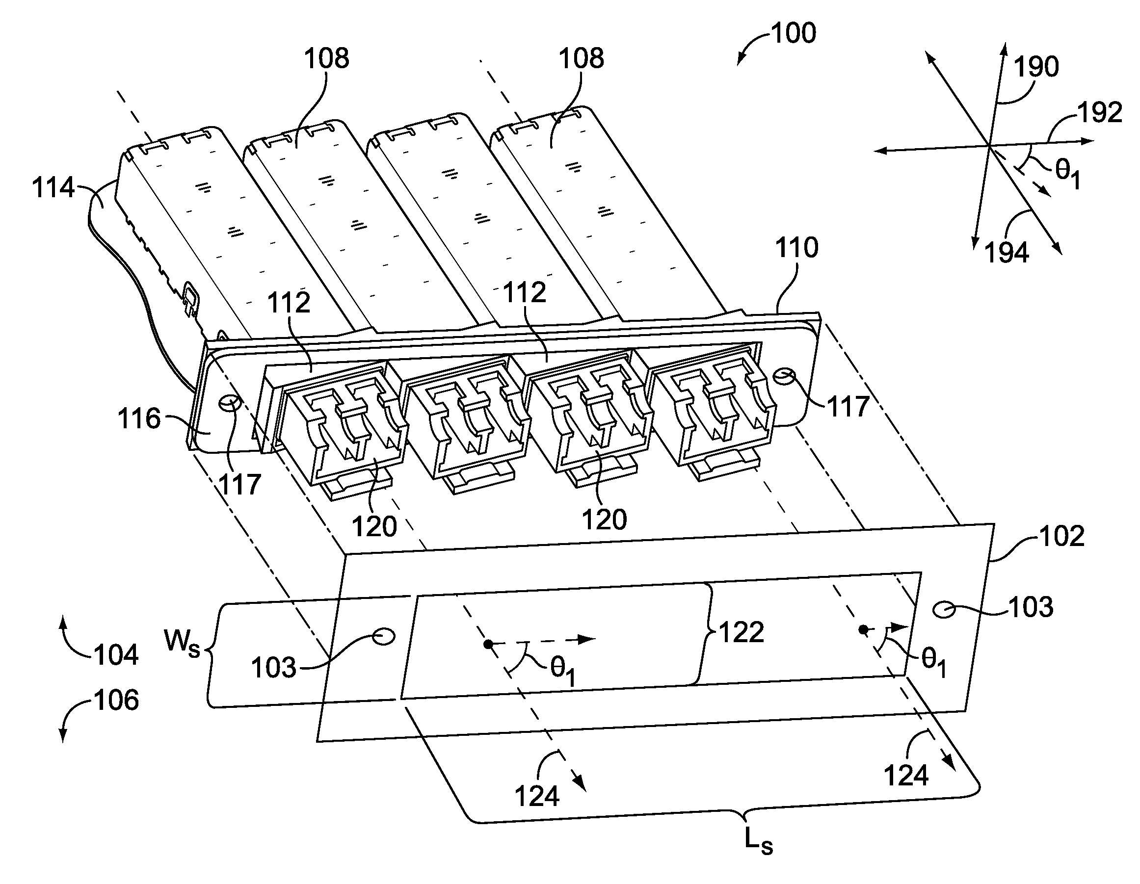
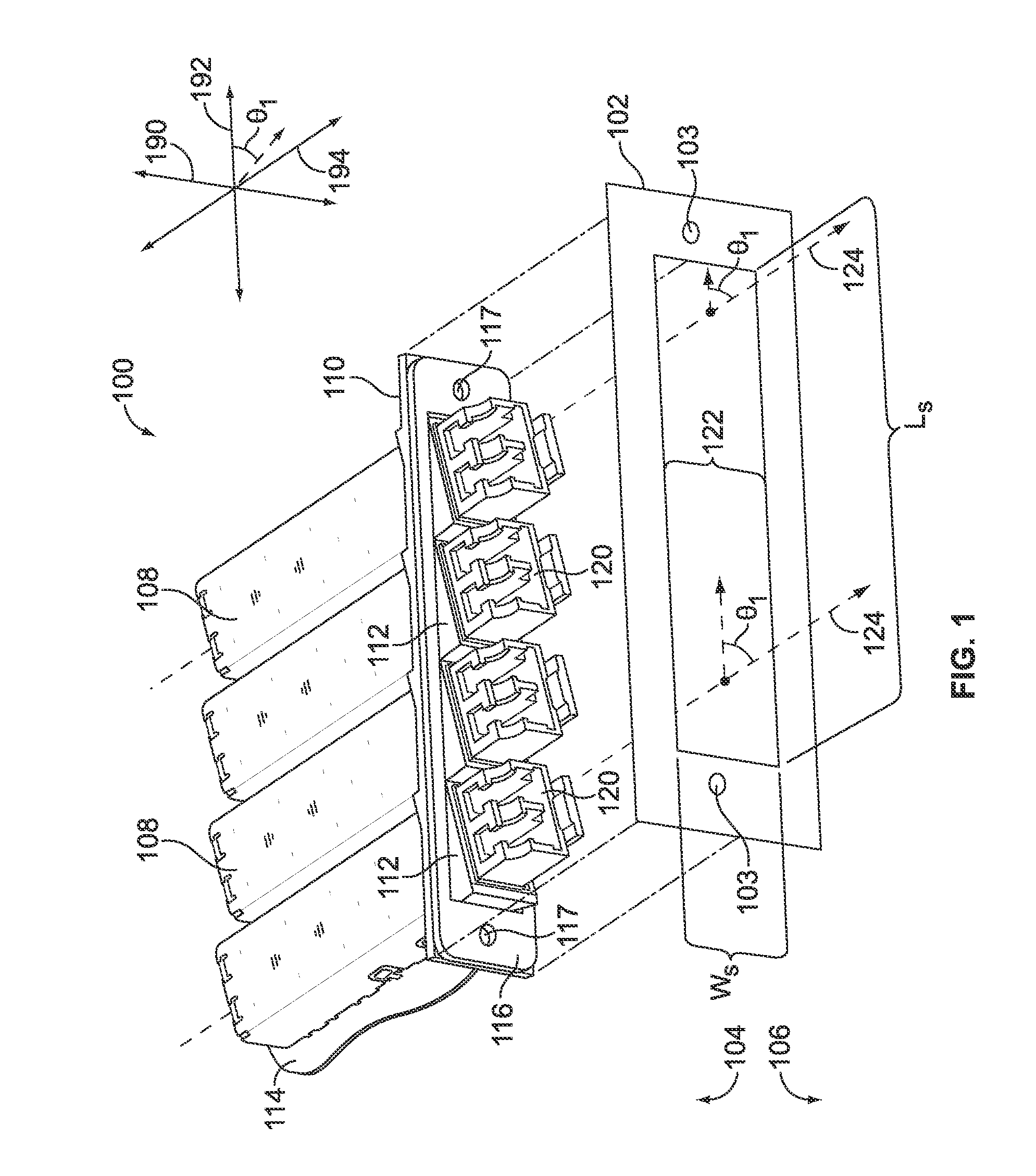
[0015]FIG. 1 is a perspective view of a receptacle assembly 100 formed in accordance with one embodiment before the receptacle assembly 100 is mounted to a support wall 102 of an electrical system (not shown). The support wall 102 may be, for example, a wall or panel in a computer or server system. The support wall 102 may separate an interior space 104 and an exterior space 106 and includes a window 122 where the receptacle assembly 100 may be mounted thereto. The window 122 has a length LS and a width WS. The receptacle assembly 100 includes one or more receptacles 108, a bracket 110 having one or more hubs 112 that are shaped to receive the receptacles 108, and a circuit board 114 that is configured to be mechanically and electrically coupled to the receptacles 108. The receptacle assembly 100 may also include a gasket 116 that extends between the bracket 110 and the support wall 102 when the receptacle assembly 100 is mounted to the support wall 102. The bracket 110 and the gask...


PUM


Abstract

A bracket configured to be mounted to a support wall. The bracket includes a panel that has opposing first and second sides that extend along a plane. The first side faces an exterior space and the second side facing an interior space. The bracket also includes a hub that is configured to receive an electronic device. The hub includes a first hub portion that extends from the first side and a second hub portion that extends from the second side toward the interior space. The first and second hub portions define a port through the panel to connect the interior and exterior spaces. The port extends along a central axis and is sized and shaped to receive and receive the device along the central axis. The central axis forms a non-orthogonal angle with respect to the plane of the first and second sides.

Description

BACKGROUND OF THE INVENTION[0001]The subject matter herein relates generally to receptacle assemblies for receiving removable electronic modules, and more particularly, to receptacle assemblies configured to receive the modules inserted in a non-orthogonal direction.[0002]Some electrical systems, such as server systems, router systems, or desktop computers, may include ports along a side or within the system that open to an exterior space of the electrical system. The ports may be configured to receive a removable electronic module. The electronic module may be, for example, a registered jack or a small-form factor pluggable (SFP) transceiver that is communicatively coupled to another system or device through a cable. For example, some SFP transceivers are communicatively coupled to the other electrical system through fiber optic cables.[0003]However, electrical systems are frequently located within confined spaces. Furthermore, the ports for receiving electronic modules may be loca...

Claims


Application Information

Patent Timeline
Patent Type & Authority Applications(United States)
IPC IPC(8): H01R13/66
CPCG02B6/3897G02B6/4249H01R13/518G02B6/4292G02B6/4277
Inventor DAVISON, ANDREW C.FLICKINGER, STEVEN LEE
Owner TE CONNECTIVITY CORP
Why Eureka
Try Eureka