
Bendable veress needle assembly

a veress needle and bendable technology, applied in the field of veress needles, can solve the problems of difficult sealing about the incision for proper insufflation, penetration and damage to and achieve the effect of reducing the likelihood that the distal tip will damage the underlying anatomical structur

Inactive Publication Date: 2010-10-14
TYCO HEALTHCARE GRP LP
View PDF27 Cites 3 Cited by
  • Summary
  • Abstract
  • Description
  • Claims
  • Application Information

AI Technical Summary

Benefits of technology

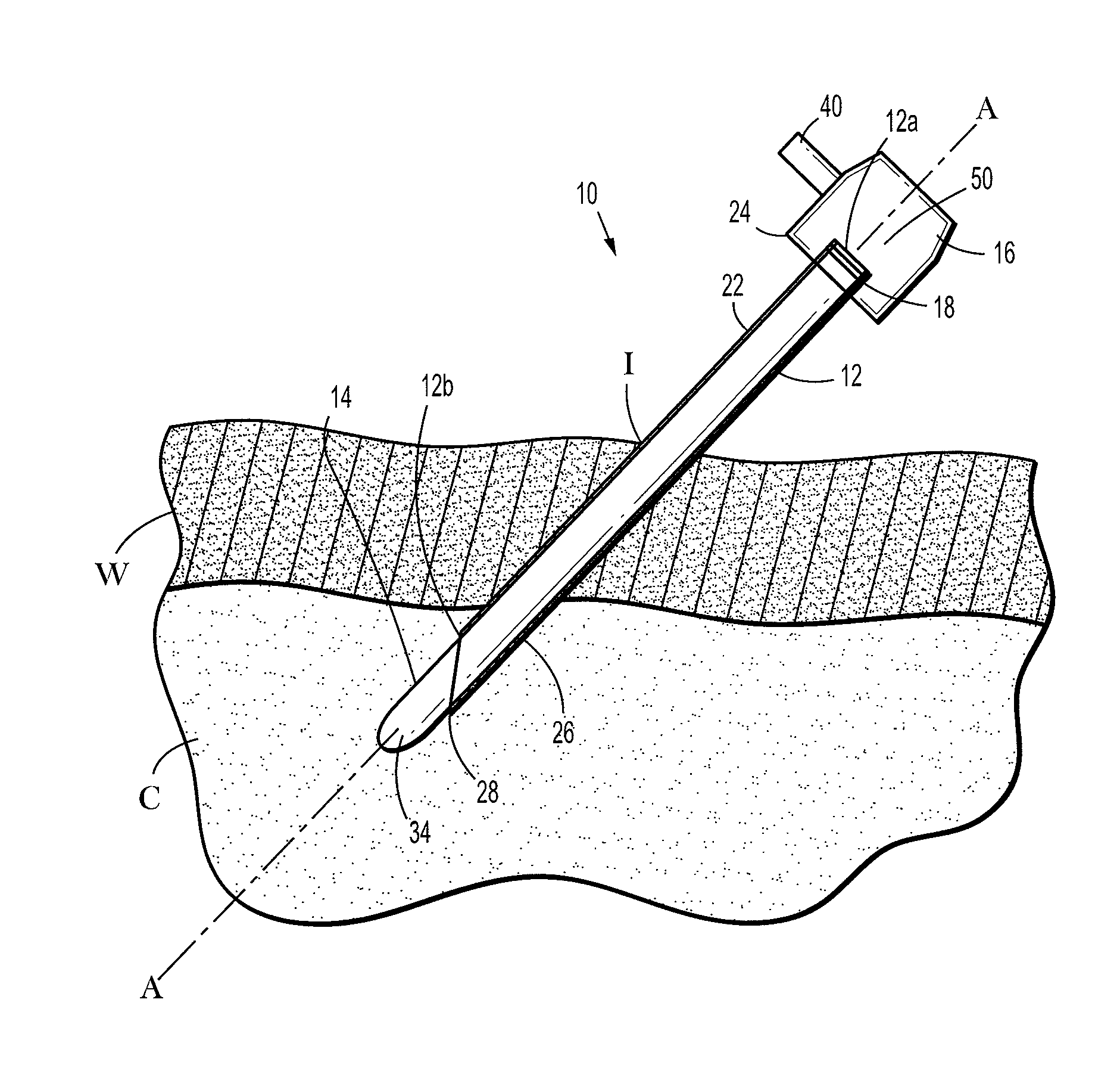
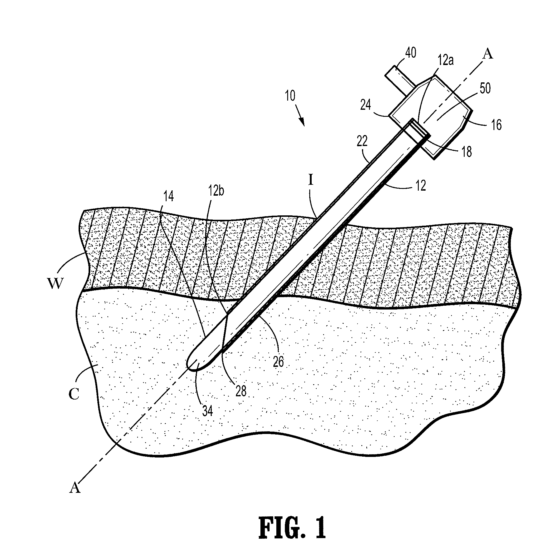
[0007]The presently disclosed bendable veress needle includes a shaft with a bendable distal region. A piercing tip is located at a distal end of the shaft. A stylet may be inserted through the shaft. The stylet may be configured for transmitting light from a light source external to the patient and / or for viewing a region of the body during or subsequent to insertion of the bendable veress needle through an incision in the patient's skin. A housing is located at a proximal end of the bendable veress needle. The housing may include an insufflation port for introducing insufflation fluids into a cavity through a bore of the bendable veress needle. The bendable veress needle may be biased towards a bent position such that, upon insertion of the bendable veress needle through an incision in the patient's skin, the distal end thereof assumes a bent position so as to minimize the likelihood that the distal tip will damage underlying anatomical structures.

Problems solved by technology

Occasionally, the surgical instruments used to form the incision result in tears or non-uniform areas around the incision making it difficult to seal about the incision for proper insufflation.
Additionally, there is a risk of over insertion resulting in penetration and damage to underlying anatomical structure.

Method used


Image

  • Bendable veress needle assembly
  • Bendable veress needle assembly
  • Bendable veress needle assembly

Examples


Embodiment Construction

[0012]Embodiments of the presently disclosed bendable veress needle assembly will now be described in detail with reference to the drawings wherein like numerals designate identical or corresponding elements in each of the several views. As is common in the art, the term ‘proximal” refers to that part or component closer to the user or operator, i.e. surgeon or physician, while the term “distal” refers to that part or component further away from the user.

[0013]Referring initially to FIG. 1, a bendable veress needle assembly 10 includes a bendable veress needle 12 having a shaft 22. The shaft 22 includes an open proximal end 12a and an open distal end 12b. The open proximal and distal ends 12a, 12b define a bore through the shaft 22. A stylet 14 is introducible through the bore of the shaft 22 and includes a lens 34. The lens 34 transmits light therethrough allowing a light source (not shown) to be coupled to the stylet 14 for illuminating the operative site in a body cavity C. Alter...


PUM


Abstract

A bendable veress needle is disclosed that has a shaft with a bendable region located near its distal end. The distal end of the bendable region includes a tissue penetrating tip. A stylet may be inserted through the bendable veress needle. A housing having an insufflation port is located at a proximal end of the bendable veress needle. A light source or imaging system may be coupled to the bendable veress needle.

Description

BACKGROUND[0001]1. Technical Field[0002]The present disclosure relates to veress needles. More particularly, the present disclosure relates to bendable veress needle assemblies used for surgical incisions.[0003]2. Background of Related Art[0004]During various surgical procedures it is often desirable to access areas within a patient's body in a relatively non-invasive manner. In laparoscopic and / or endoscopic surgeries, a small incision is formed in the body to allow passage of various surgical instrumentation. Often these incisions are formed using a hollow pointed needle also referred to as a veress needle.[0005]In some specific surgeries, such as, for example, hernia repair surgery, a small incision is made through the abdominal wall to access tissue within the abdominal cavity. Some such procedures require insufflation of the abdominal cavity to provide an operative space. This is typically accomplished with the insertion of a cannula through the incision. Additional incisions m...

Claims


Application Information

Patent Timeline
IPC IPC(8): A61B17/34
CPCA61B17/3417A61B17/3474A61B2018/00982A61B2017/00867A61B2017/00946A61B2017/003
Inventor DAVIS, MICHAELHATHAWAY, PETER
Owner TYCO HEALTHCARE GRP LP
Learn More