Medical cutting device and medical cutting training device

a cutting device and cutting training technology, applied in the field of medical cutting devices and cutting training devices, can solve the problems of inability to accurately evaluate cutting, requires an expensive device, and cannot measure the load applied to the cutting tool during cutting, so as to achieve the effect of avoiding excessive cutting and easy obtaining changes

Inactive Publication Date: 2010-10-14
MORITA MFG CO LTD
View PDF7 Cites 20 Cited by
  • Summary
  • Abstract
  • Description
  • Claims
  • Application Information

AI Technical Summary

Benefits of technology

[0008]In a clinical practice, it is possible to avoid excessive cutting if a load applied to a cutting tool during cutting is obtained. However, workability is valued in a clinical practice, and thus it is required to provide a handpiece with a configuration for measuring a load applied to a cutting tool during cutting in a handpiece within a range of, for example, the same shape as that of a normally-used handpiece.
[0036]According to the medical cutting device of the fourteenth aspect of the present invention, the medical cutting device capable of detecting a load applied to a cutting tool or a load vector is used, which enables instant evaluations of cutting training based on objective data.

Problems solved by technology

In the cutting training described in Japanese Patent Application Laid-Open No. 10-97187, evaluations are made only after the shape of the artificial tooth which is cut after training is measured, and thus real-time evaluations of cutting cannot be made.
In addition, the cutting training described in Japanese Patent Application Laid-Open No. 10-97187 requires an expensive device such as a three-dimensional shape measuring device for measuring a shape of an artificial tooth.
Moreover, in the cutting training described in Japanese Patent Application Laid-Open No. 2000-298427, a trail of the handpiece is recorded, but a load applied to a cutting tool during cutting cannot be measured.

Method used


Image

  • Medical cutting device and medical cutting training device
  • Medical cutting device and medical cutting training device
  • Medical cutting device and medical cutting training device

Examples


first preferred embodiment

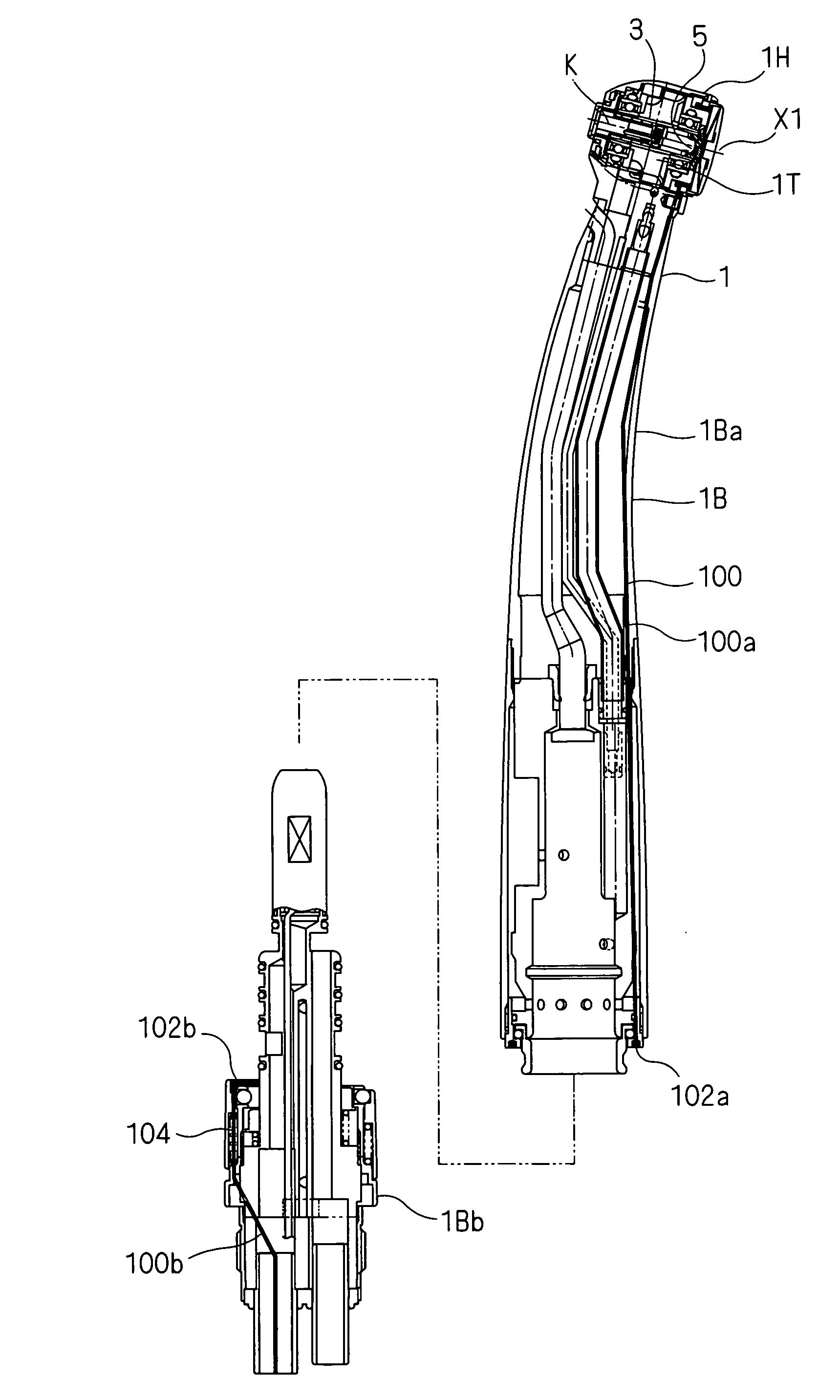
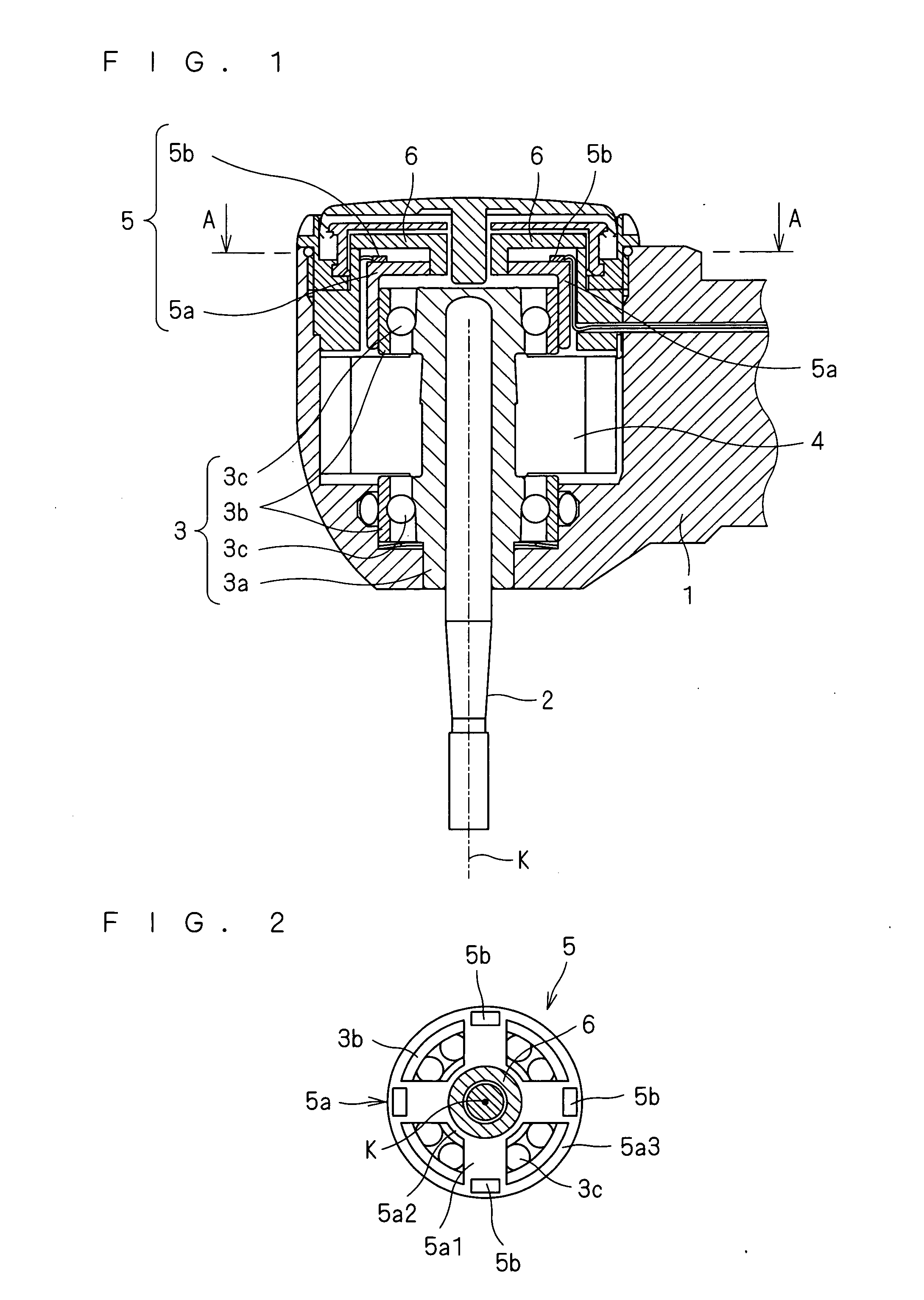
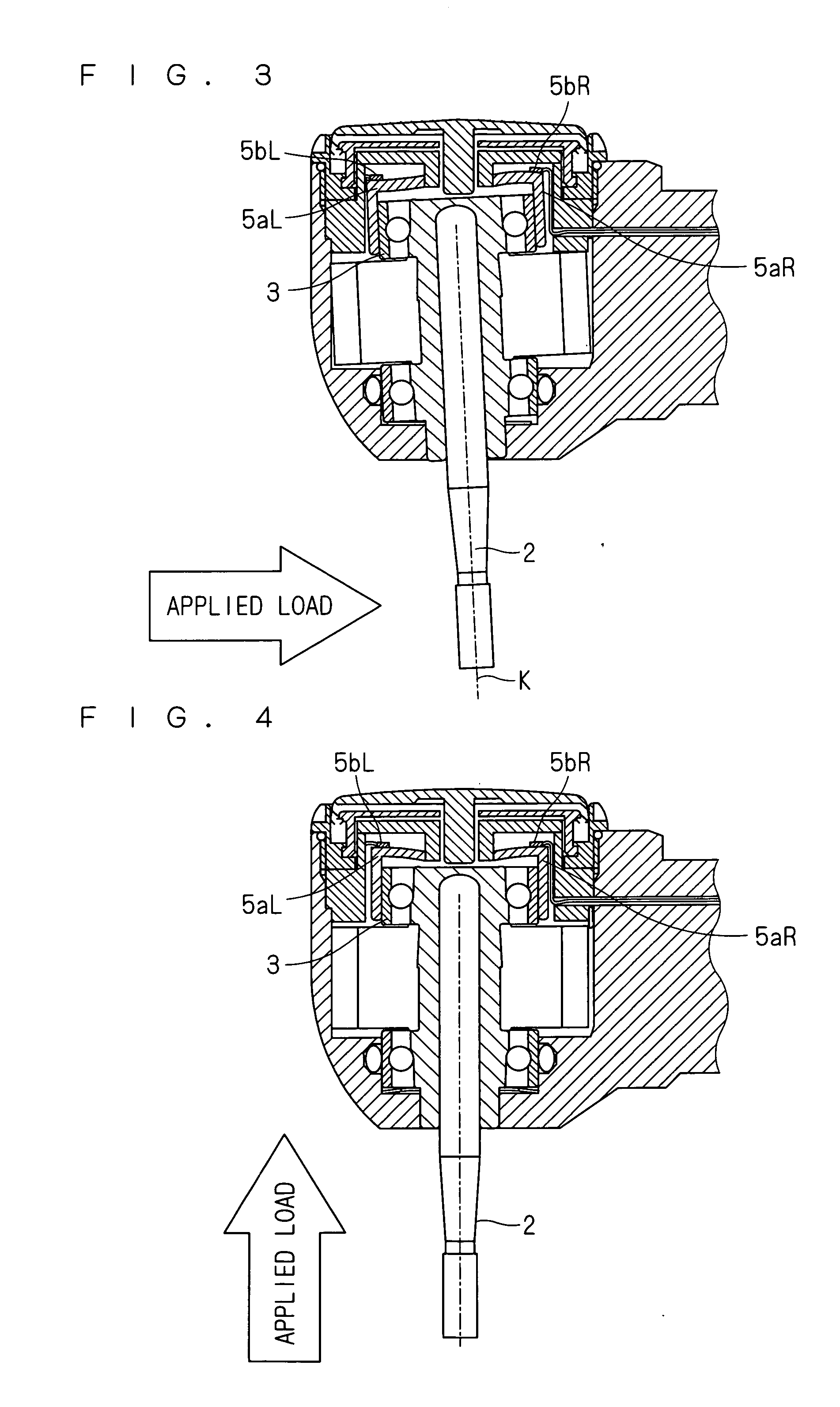
[0052]In a medical cutting device according to this preferred embodiment, a load detecting unit which detects a load applied to a cutting tool is provided in a housing. Specific description will be given of a configuration using a strain gauge as a load detecting unit in the medical cutting device according to this preferred embodiment. FIG. 1 is a cross-sectional view of an air turbine handpiece which is the medical cutting device according to this preferred embodiment. The air turbine handpiece shown in FIG. 1 houses, in a housing 1, a cutting tool supporting unit 3 which supports a cutting tool 2, a turbine rotor 4 for driving the cutting tool 2, and a load detecting unit 5 which detects a load applied to the cutting tool 2.

[0053]The housing 1 is formed of the same material and has approximately the same shape and scale as those of a housing of a conventionally-used air turbine handpiece. Note that compared with a conventional housing, the housing 1 needs to obtain more space by ...

second preferred embodiment

[0090]Also in a medical cutting device according to this preferred embodiment, as in the first preferred embodiment, the load detecting unit which detects a load applied to the cutting tool is provided inside the housing. Differently from the first preferred embodiment, the medical cutting device according to this preferred embodiment has a configuration in which not the strain gauges, but pressure sensors are used in the load detecting unit. FIG. 11 is a cross-sectional view of an air turbine handpiece which is the medical cutting device according to this preferred embodiment. In the air turbine handpiece shown in FIG. 11, the housing 1 houses the cutting tool supporting unit 3 which supports the cutting tool 2, the turbine rotor 4 for driving the cutting tool 2, and a load detecting unit 7 which detects a load applied to the cutting tool 2. Note that the same components of the air turbine handpiece shown in FIG. 11 as those of the air turbine handpiece shown in FIG. 1 are denoted ...

third preferred embodiment

[0097]The medical cutting device which obtains a load applied to the cutting tool 2 during cutting has been described in the first and second preferred embodiments. The medical cutting device is capable of being used in clinical practice as well as training. Further, description will be given of a medical cutting training device which includes the medical cutting device and is capable of making evaluations of cutting in training.

[0098]FIG. 14 is a block diagram of the medical cutting training device according to this preferred embodiment. The medical cutting training device shown in FIG. 14 is configured such that a judging unit 17 is added to the medical cutting device shown in FIG. 5. The judging unit 17 is formed within the CPU 13, and compares a load or a load vector applied to the cutting tool 2 which is obtained from the control circuit 14 with a predetermined judgment standard, to thereby make evaluations and judgments of a cutting operation. As the predetermined judgment sta...


PUM


Abstract

Provided is a medical cutting device including a housing, a cutting tool, a tool supporting unit and a load detecting unit. The housing supports the tool supporting unit and the load detecting unit. The tool supporting unit supports the cutting tool. The load detecting unit detects a load applied to the cutting tool.

Description

BACKGROUND OF THE INVENTION[0001]1. Field of the Invention[0002]The present invention relates to a medical cutting device and a medical cutting training device including the same.[0003]2. Description of the Background Art[0004]In dental treatments, a treatment to cut teeth with a handpiece which is a medical cutting device is performed. It is required to complete a cutting training for acquiring this medical technique. In the cutting training, as described in Japanese Patent Application Laid-Open No. 10-97187, a shape of an artificial tooth which is cut after training is measured, and the measured shape is compared with a cutting shape of a trainer, to thereby make evaluations.[0005]Further, Japanese Patent Application Laid-Open No. 2000-298427 proposes the method of recording a trail of a handpiece with an imaging camera for making real-time evaluations of cutting training.SUMMARY OF THE INVENTION[0006]In the cutting training described in Japanese Patent Application Laid-Open No. 1...

Claims


Application Information

Patent Timeline
Patent Type & Authority Applications(United States)
IPC IPC(8): A61B17/00
CPCA61B17/1622A61B17/32G09B23/283A61C1/08A61C1/186A61B2019/464A61B2090/064
Inventor KAJI, RYOSUKEJIKUHARA, HIROFUMI
Owner MORITA MFG CO LTD
Why Eureka
Try Eureka