Actuated prosthesis for amputess

a technology for amputees and prostheses, applied in the field of amputee actuated prostheses, can solve the problems of difficult task of prosthesis for amputees, difficult task for leg prosthesis, and limited conventional leg prosthesis

Inactive Publication Date: 2010-10-14
NATIONAL BANK OF CANADA
View PDF106 Cites 48 Cited by
  • Summary
  • Abstract
  • Description
  • Claims
  • Application Information

AI Technical Summary

Benefits of technology

[0013]In accordance with another broad aspect of the present invention, there is provided an improved actuated leg prosthesis comprising a knee member, a socket connected to the knee member, an elongated trans-tibial member, an artificial foot connected under a bottom end of the trans-tibial member, and a linear actuator. A first pivot assembly allows to operatively connect the trans-tibial member to the knee member. The first pivot assembly defines a first pivot axis that is perpendicular to a main longitudinal axis of the trans-tibial member. A second p

Problems solved by technology

All these prostheses have the difficult task of giving to these amputees a life as normal as possible.
The task is particularly difficult for leg prostheses due in part to the complexity of human locomotion.
Conventional leg prostheses are very limited compared to a real human leg and some needs were thus not entirely fulfilled by them.
According to amputees, specific conditions of use of conventional leg prostheses, such as repetitive movements and continuous loading, typically entail problems such as increases in metabolic energy expenditures, increases of socket pressure, limitations of locomotion speeds, discrepancies in the locomotion movements, disruptions of postural balance, disruptions of the pelvis-spinal column alignment, and increases

Method used


Image

  • Actuated prosthesis for amputess
  • Actuated prosthesis for amputess
  • Actuated prosthesis for amputess

Examples


example

Calculation for the Optimal Angle

[0081]One can assume the following technical specifications:

[0082]a geometrical volume corresponding to the anthropometrical volume of a natural shank of an individual having a weight of 70 kg and a height of 170 cm;

[0083]a maximal distance r set at 0.055 m, that is r<0.055 m;

[0084]a minimal and a maximal length LT set at 0.3 m and 0.4 m respectively, that is 0.3 mT<0.4 m; and

[0085]a minimal and a maximal distance dT set at −0.015 m and +0.015 m, that is −0.015 mT<+0.015 m.

[0086]The geometrical model can be defined with the following equations:

β=π-θfix-α-θKEquation1LA=LT2+dT2Equation2α=arctan(dTLT)Equation3L2=LA2+r2-2·LAr·cosβEquation4br=r·LA·sinβLA2+r2-2·LA·r·cosβEquation5

[0087]where

[0088]θK Knee angle, ∠DOA

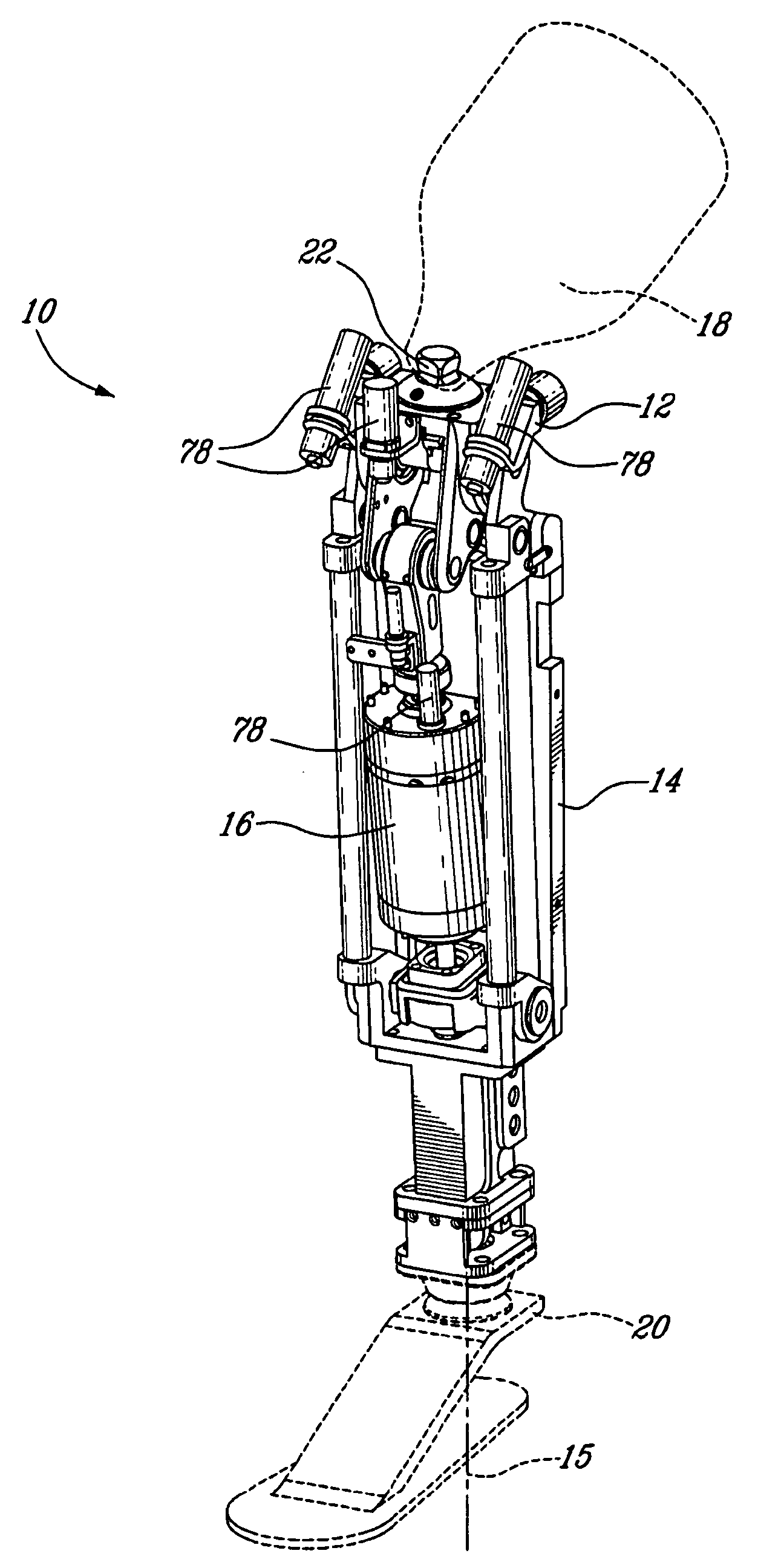
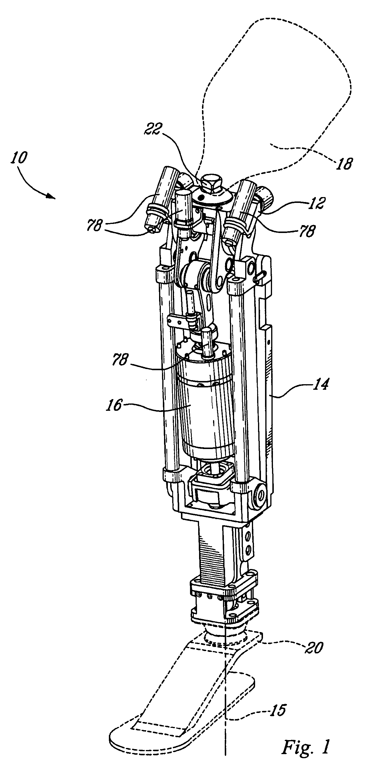
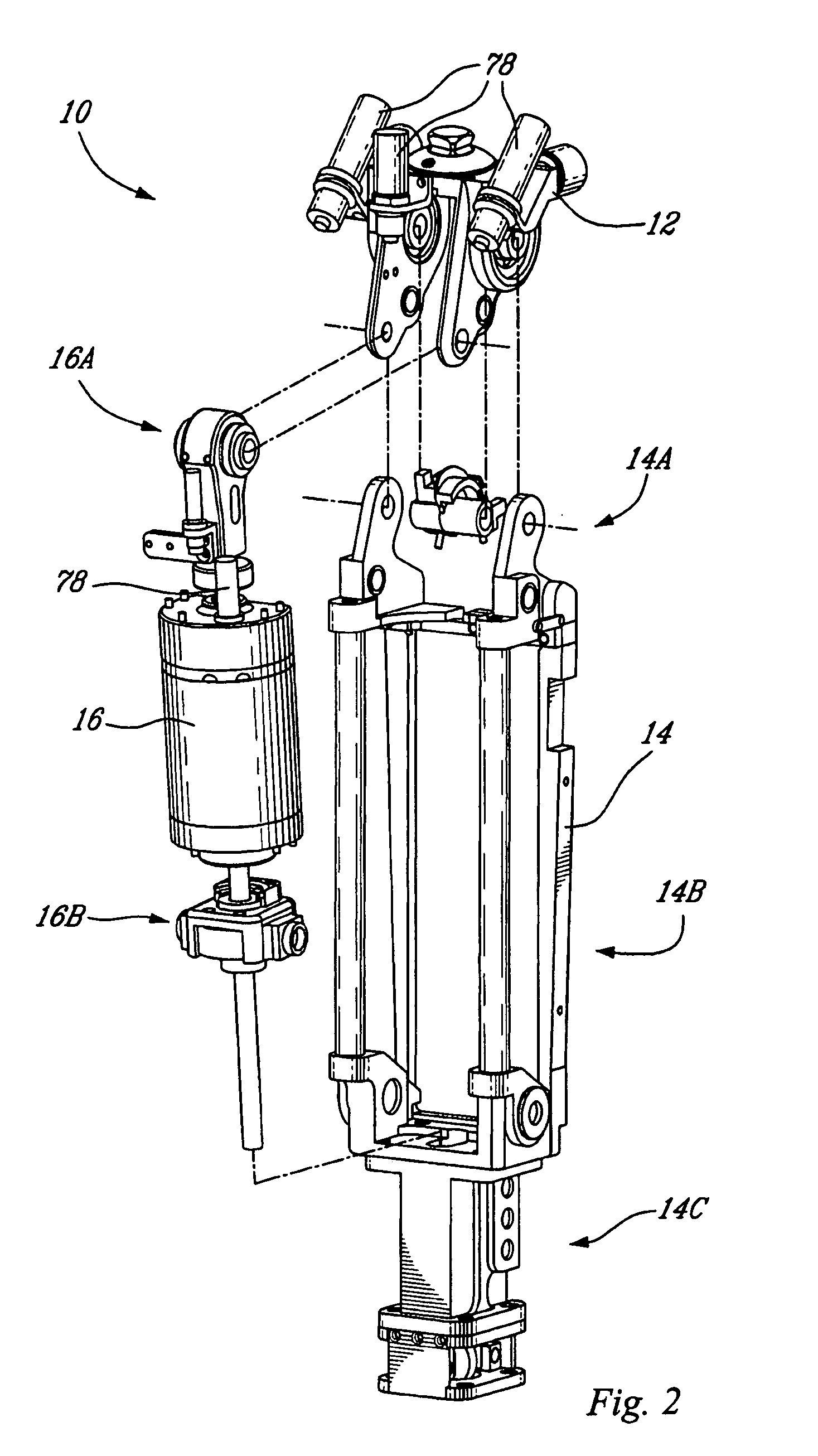
[0089]r Distance between the center of rotation “O” of the knee member (12) and the attachment point of the actuator (16) on the knee member (12)

θfix Angle between r and the stump's center axis, ∠EOC

[0090]LA Distance between the center of rotatio...


PUM


Abstract

The actuated leg prosthesis comprises a knee member, a socket connector provided over the knee member, an elongated trans-tibial member having a bottom end under which is connected an artificial foot, and a linear actuator. A first pivot assembly allows to operatively connect the trans-tibial member to the knee member. A second pivot assembly allows to operatively connect an upper end of the actuator to the knee member. A third pivot assembly allows to operatively connect a bottom end of the actuator to the bottom end of the trans-tibial member. The prosthesis can be provided as either a front actuator configuration or a rear actuator configuration.

Description

RELATED APPLICATIONS[0001]The present application is a continuation of U.S. patent application Ser. No. 10 / 721,764, filed Nov. 25, 2003, which is a continuation-in-part of U.S. patent application Ser. No. 10 / 463,495, filed Jun. 17, 2003, now U.S. Pat. No. 7,314,490, which claims the benefit of priority of U.S. Provisional Patent Application No. 60 / 405,281, filed Aug. 22, 2002, U.S. Provisional Patent Application No. 60 / 424,261, filed Nov. 6, 2002, and U.S. Provisional Patent Application No. 60 / 453,556, filed Mar. 11, 2003, each of which is hereby incorporated by reference in its entirety.BACKGROUND[0002]1. Field[0003]The present invention relates to an actuated prosthesis for amputees, particularly but not exclusively for a leg prosthesis for above knee amputees.[0004]2. Description of Related Art[0005]Over the years, many kinds of prostheses have been devised in effort to replace the limbs that amputees have lost. In particular, many efforts have been made to develop prostheses tha...

Claims


Application Information

Patent Timeline
IPC IPC(8): A61F2/78A61F2/00A61F2/50A61F2/60A61F2/64A61F2/66A61F2/68A61F2/70A61F2/76
CPCA61F2/644A61F2/64A61F2/6607A61F2/68A61F2002/30359A61F2002/5041A61F2002/607A61F2002/6614A61F2002/6685A61F2002/701A61F2002/704A61F2002/705A61F2002/741A61F2002/762A61F2002/7625A61F2002/7635A61F2002/764A61F2220/0033A61F2/66A61F2/70A61F2/741A61F2/60
Inventor BEDARD, STEPHANEROY, PIERRE-OLIVIER
Owner NATIONAL BANK OF CANADA
Why Eureka
Try Eureka