Shower enclosure design and assembly methods using prefabricated shower benches

a shower enclosure and prefabricated technology, applied in the field of shower enclosure design and assembly, can solve the problems of time-consuming and labor-intensive process of creating the enclosed shower, water from the shower not draining properly, and difficulty in tiling the shower enclosur

Active Publication Date: 2010-10-21
TILE REDI
View PDF22 Cites 26 Cited by
  • Summary
  • Abstract
  • Description
  • Claims
  • Application Information

AI Technical Summary

Problems solved by technology

Most tile-covered shower enclosures are created using complicated construction methods.
The process of creating the enclosed shower is time-consuming and requires a certain degree of skill in order to maintain the proper pitch and uniformity in shaping the floor.
Irregularities in the pitch of the floor can cause water from the shower not to drain properly or make tiling the shower enclosure difficult.
The liners are also susceptible to punctures or leaks and may be difficult for the installer to properly form square corners at the intersection of the shower sidewalls and floor.
Additionally, the mortar layer used to create the floor is necessarily thick in order to form a sloped surface, therefore the time required for the floor to cure before applying tile may be quite long (e.g., greater than 24 hours).
However, these prefabricated shower modules contain weaknesses in the design which add cost to the final product.
However, the mold or “tool” for creating each unit can be quite expensive, thus a manufacturer generally limits the number of tools for producing each module.
Further, each size module requires a specific mold, thus the manufacturer

Method used


Image

  • Shower enclosure design and assembly methods using prefabricated shower benches
  • Shower enclosure design and assembly methods using prefabricated shower benches
  • Shower enclosure design and assembly methods using prefabricated shower benches

Examples


Embodiment Construction

)

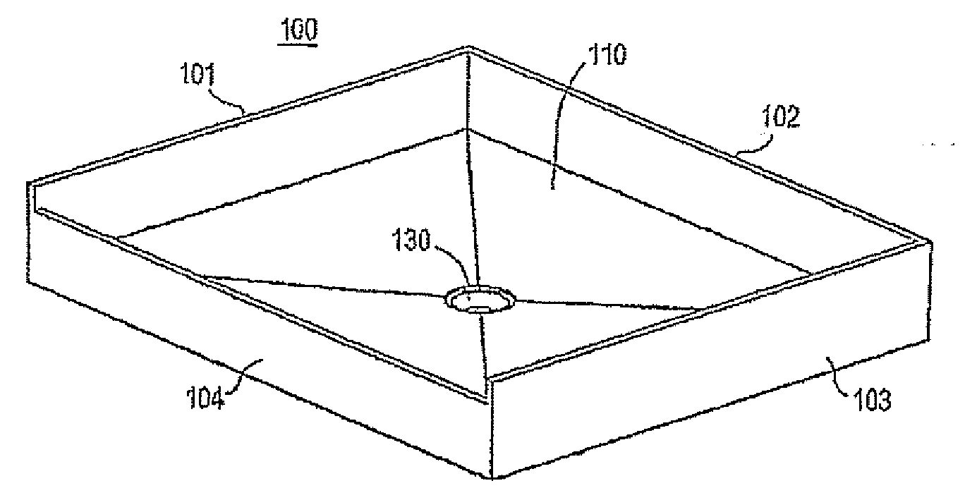
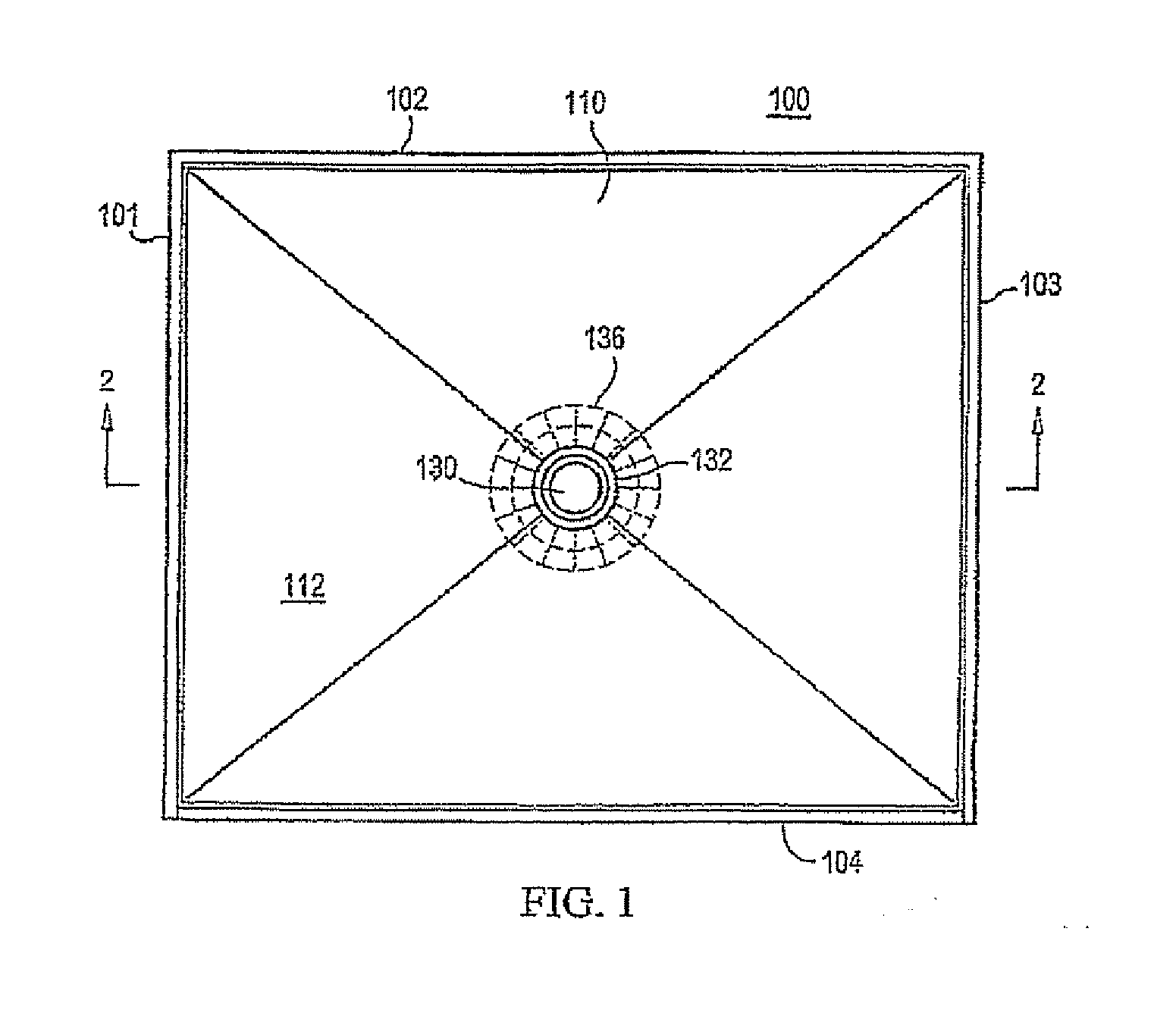
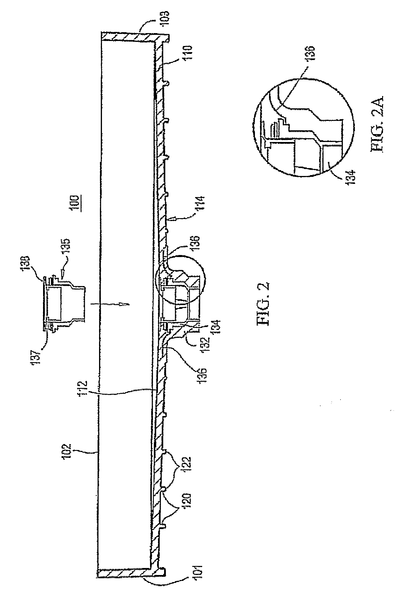
[0064]Before describing in detail exemplary embodiments that are in accordance with the present invention, it should be observed that the embodiments reside primarily in combinations of apparatus components and processing steps related to implementing a method for improving manufacturability of a pre-molded leak-proof shower module having surfaces for receiving shower tile or stone thereon and the associated shower module. Accordingly, the apparatus and method components have been represented where appropriate by conventional symbols in the drawings, showing only those specific details that are pertinent to understanding the embodiments of the present invention so as not to obscure the disclosure with details that will be readily apparent to those of ordinary skill in the art having the benefit of the description herein.

[0065]In this document, relational terms, such as “first” and “second,”“top” and “bottom,” and the like, may be used solely to distinguish one entity or element fro...


PUM

PropertyMeasurementUnit
Areaaaaaaaaaaa
Dimensionaaaaaaaaaa

Abstract

Methods and apparatus for creating a shower or bath enclosure, in which, given a predetermined area in which to create the shower or bath, a given prefabricated water proof bath or shower floor module is too small to occupy the entire available enclosure space. The apparatus includes the use of one or more additional enclosure components, such as one or more shower benches, to occupy a space between an edge or edges of the floor module and the exterior boundary(ies) of the enclosure space. One of the disclosed methods includes the steps of:
    • installing wall studs to generally frame out the enclosure space within which the shower or bath will reside;
    • placing a prefabricated floor module in the enclosure space, said module defining an outer peripheral edge, said module being smaller in at least one dimension than an area defined by the boundary;
    • placing a shower or bath bench support frame in the space such that the support frame is adjacent at least one of the wall studs and the floor module;
    • placing a shower or bath bench on the support frame so that the bench occupies at least a portion of any open space(s) or gaps between the outer peripheral edge of the floor module and the boundary of the proposed enclosure space;
    • attaching wallboard to the studs such that a lower edge of the wallboard rests above and is substantially in registry with an upper peripheral edge of a sidewall of the shower or bath bench; and
    • installing at least one of tile, stone and marble on the wallboard, the module, and the prefabricated bench, thereby resulting in a tiled shower or bath.

Description

CROSS-REFERENCE TO RELATED APPLICATIONS[0001]The present application is a continuation in part of prior co-pending U.S. patent application Ser. No. 11 / 724,913 filed on Mar. 17, 2007, which was commonly filed with the following U.S. patent applications: Ser. No. 11 / 724,873, Attorney Docket No. 8540-06001, entitled “Ribbed Prefabricated Polyurethane Shower Module,” U.S. patent application Ser. No. 11 / 724,914, Attorney Docket No. 8540-07003, entitled “Method for Manufacturing a Prefabricated Modular Shower Curb and Associated Modular Shower Curb,” U.S. patent application Ser. No. 11 / 725,113, Attorney Docket No. 8540-07004, entitled “Prefabricated Shower Pan Having Varying Sidewall Heights and Method of Attaching a Modular Curb Thereto,” U.S. patent application Ser. No. 11 / 724,912, Attorney Docket No. 8540-07005, entitled “Improved Drain Wall for a Prefabricated Shower Module,” and U.S. patent application Ser. No. 11 / 725,112, Attorney Docket No. 8540-07006, entitled “Improved Method for...

Claims


Application Information

Patent Timeline
IPC IPC(8): B23P17/04
CPCA47K3/40Y10T29/49826Y10T29/49716A47K3/283
Inventor COOK, JOSEPH R.
Owner TILE REDI
Why Eureka
Try Eureka