
Intelligent battery system

a battery system and intelligent technology, applied in the field of intelligent battery systems, can solve the problems of unfavorable battery powered systems, inability to plug such workstations into a standard wall outlet, troublesome powering such mobile workstations, etc., and achieve the effect of low-voltage shutdown capability

Inactive Publication Date: 2010-10-21
ANTONBAUER
View PDF9 Cites 37 Cited by
  • Summary
  • Abstract
  • Description
  • Claims
  • Application Information

AI Technical Summary

Benefits of technology

"The present invention provides an intelligent battery system for powering mobile workstations. The system allows for swapping out batteries without interrupting power to the workstation and also prevents batteries from being accidentally removed. The system can maintain power even if the main batteries are spent or accidentally removed. It also provides a warning to the user of the system of impending low battery capacity. The system can run multiple batteries in parallel to simultaneously power the workstation and also regulates voltage output. It has low voltage shutdown capability and can be retrofit on numerous existing medical cart applications. The system includes two snap-on battery interface brackets for accommodating two hot-swap batteries, a main hot-swap battery, and a secondary hot-swap battery, and a third snap-on bracket to hold a spare battery. The spare battery includes an integrated circuit for detecting the removal of either or both hot-swap batteries, for detecting when either or both hot-swap batteries are low in capacity, and for providing backup power."

Problems solved by technology

Powering such mobile workstations, however, has proven troublesome.
As will be readily appreciated, it is undesirable to plug such workstations into a standard wall outlet, as power will be interrupted when moving from room to room or patient to patient.
Battery powered systems have attempted to solve this problem, however, even known battery powered systems have objectionable shortcomings.
These known batteries for powering mobile workstations, however, are difficult to replace when spent.
Moreover, existing systems make it is necessary to interrupt power to the cart when changing such batteries, therefore interrupting work flow and potentially resulting in the loss of data.

Method used


Image

  • Intelligent battery system
  • Intelligent battery system
  • Intelligent battery system

Examples


Embodiment Construction

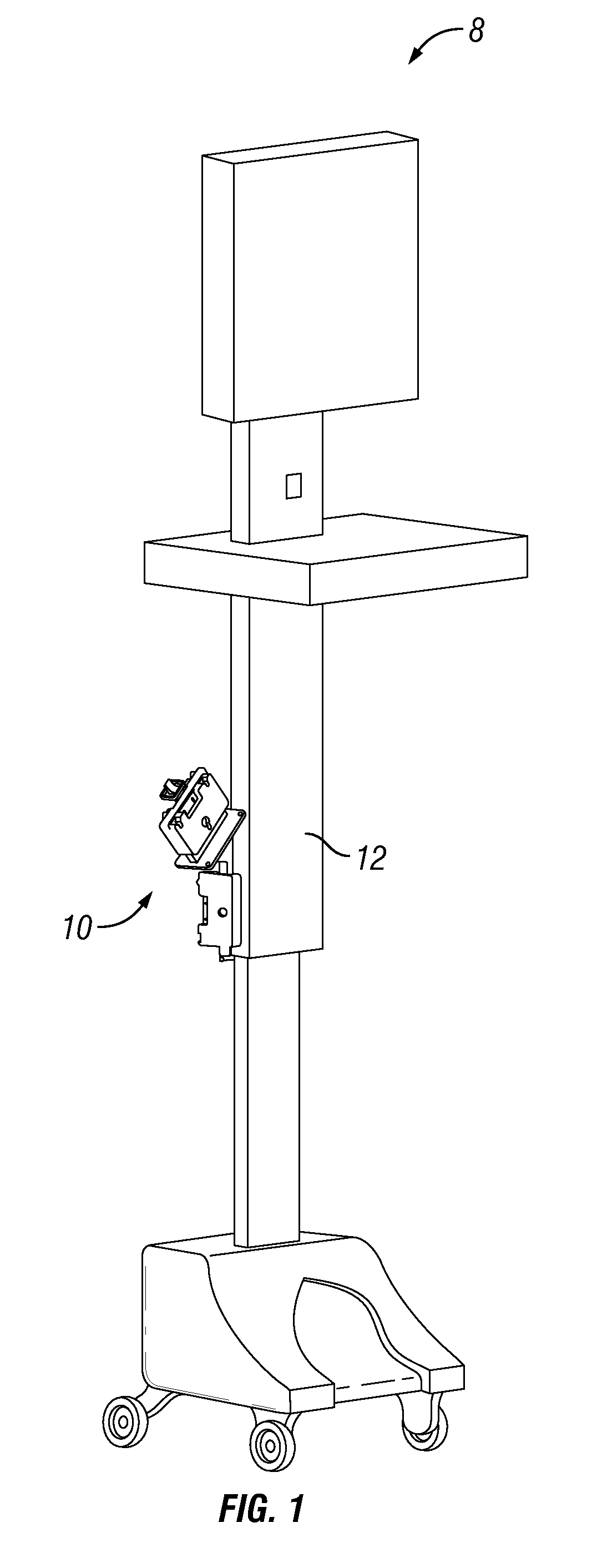
[0027]The present invention is directed to an intelligent battery system 8 for powering mobile workstations.

[0028]More particularly, and as shown in FIG. 1, the present invention is a multi-cell battery system that powers an in-hospital mobile medical cart workstation. The wireless workstation is typically utilized by nurses to dispense patient care throughout a hospital environment. Preferably the battery system may be used with NiMH, Li-Ion, NiCad, SLA and Li-Poly batteries, although batteries with any battery chemistry known in the art may be used with the present system.

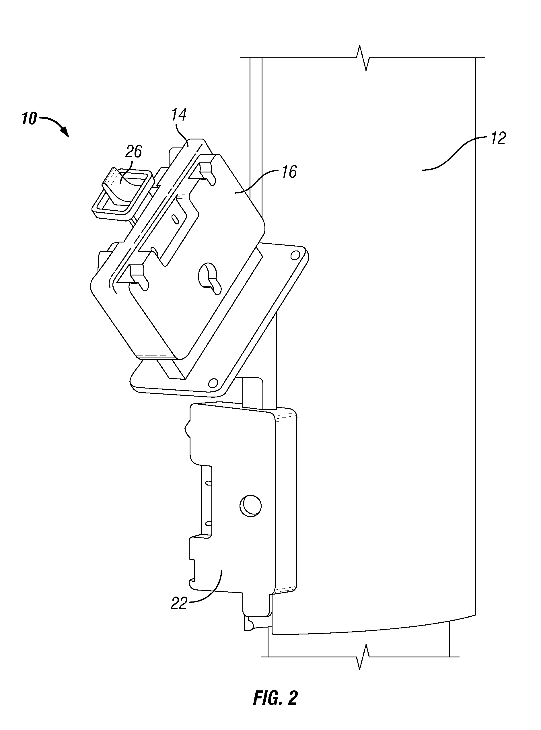
[0029]As best shown in FIG. 2, the intelligent battery system of the present invention includes a “hot-swap” device 10 that is mounted to the side of a medical cart or other mobile workstation 12. As used herein, “hot-swap” refers to a system / device that allows a user to swap batteries in or out of the device without interrupting power to the workstation. The device 10 includes two snap-on battery interface brack...


PUM


Abstract

An intelligent battery system for powering a mobile workstation includes a mounting block having a first battery interface bracket for the releasable attachment of a first battery, a second battery interface bracket for the releasable attachment of a second battery and a third battery interface bracket for the releasable attachment of a backup battery, and a power control circuit functionally integrated with the mounting block and being capable of detecting a change in status of at least one of the first and second batteries and routing the flow of electrical power from the first, second and backup batteries in dependence thereon.

Description

CROSS REFERENCE TO RELATED APPLICATIONS[0001]This application claims the benefit of U.S. Provisional Application Ser. No. 61 / 170,181, filed on Apr. 17, 2009, which is herein incorporated by reference in its entirety.FIELD OF THE INVENTION[0002]The present invention relates generally to battery systems and, more particularly, to an intelligent battery system for powering mobile workstations.BACKGROUND OF THE INVENTION[0003]Mobile computer workstations are desirable in numerous settings to make computer use more convenient and to make computers more accessible. For example, mobile workstations in the form of mobile medical carts are used in hospitals so that nurses and technicians may continually update patient information and treatment information from a variety of locations. In the hospital setting, for example, mobile workstations or mobile medical carts allow nurses to input changes in patient treatment or otherwise dispense patient care throughout the hospital environment while t...

Claims


Application Information

Patent Timeline
Patent Type & Authority Applications(United States)
IPC IPC(8): H02J9/00
CPCG06F1/263H01M10/482H02J7/0068H02J2007/0067H02J7/0013H02J7/0025Y02E60/10
Inventor MURTHA, JOSEPHROSS, MARKMARKLAND, JAMESFREDERICK, WILLIAMHULTMAN, CARLACCARDI, MICHAEL
Owner ANTONBAUER
Learn More