All-optical fiber interferometer

an optical fiber interferometer and all-optical technology, applied in the field of optical fiber-based devices manufacturing, can solve the problems of modal guiding behavior being restrictively dependent, it is difficult to form two identical 3-db long-period fiber grating pairs in a pcf, and the approach suffers from several construction limitations, so as to improve the coupling efficiency, simplify the connectorization, and introduce minimal losses

Inactive Publication Date: 2010-10-21
INST DE CIENCIAS FOTONICAS +1
View PDF4 Cites 10 Cited by
  • Summary
  • Abstract
  • Description
  • Claims
  • Application Information

AI Technical Summary

Benefits of technology

[0015]When splicing together two MOFs, or a MOF and a conventional optical fiber, the air-holes of the MOF fragment collapse completely in the vicinity of the splice. Collapsing of the voids in a short region of the MOF is not a serious drawback of fusion splices, since it may introduce minimal losses when heating time and an electric current of the conventional electric-arc process for fusion splicing is conveniently (approximately 50%) reduced. By collapsing the air-holes, a zone of the MOF is transformed into a solid multimode optical fiber. In addition, the collapsing of the microscopic air-holes is exploited to hermetically seal the end of MOFs which simplifies their connectorization and increases their coupling efficiency. The cleaving and splicing processes take just a few minutes and can be carried out with standard fiber optics equipment.
[0019]Thus, in the all-optical fiber interferometer constructed with these two fusion splices, the transmitted optical power present maxima at certain wavelengths and minima at others. The period of the intensity pattern is inversely proportional to the length of the MOF between the two splices. This interferometer exhibits truly sinusoidal and stable interference spectra observed over a broad wavelength range (around 800 nanometers bandwidth). Given the single frequency nature of the pattern only two modes (fundamental mode and one high order mode) are excited over a wavelength range from 650 to 1600 nanometers approximately. In addition, the visibility of intensity pattern that can be achieved (greater than 80%) indicates nearly perfect interference between the two modes.

Problems solved by technology

These approaches suffer from several construction limitations, though.
But, unlike in conventional single-mode fibers, it is rather difficult to form two identical 3-dB long-period fiber grating pairs in a PCF.
Mechanically inducing two identical long-period fiber gratings in the PCF, as Jong H. Lim et al. propose, in order to make an all-fiber Mach-Zehnder interferometers helps to study the properties of the cladding modes guided along the PCF, but it does not achieve to have them controlled and makes the modal guiding behavior restrictively dependent upon the severe construction requirements of the long-period fiber grating pairs in the PCF.
Nonetheless, the disadvantage of this interferometer is an irregular and unpredictable oscillatory pattern.
All these techniques and others so far reported for interferometer fabrication based on MOFs present severe challenges in terms of complexity and / or manufacturability.

Method used


Image

  • All-optical fiber interferometer
  • All-optical fiber interferometer
  • All-optical fiber interferometer

Examples


Embodiment Construction

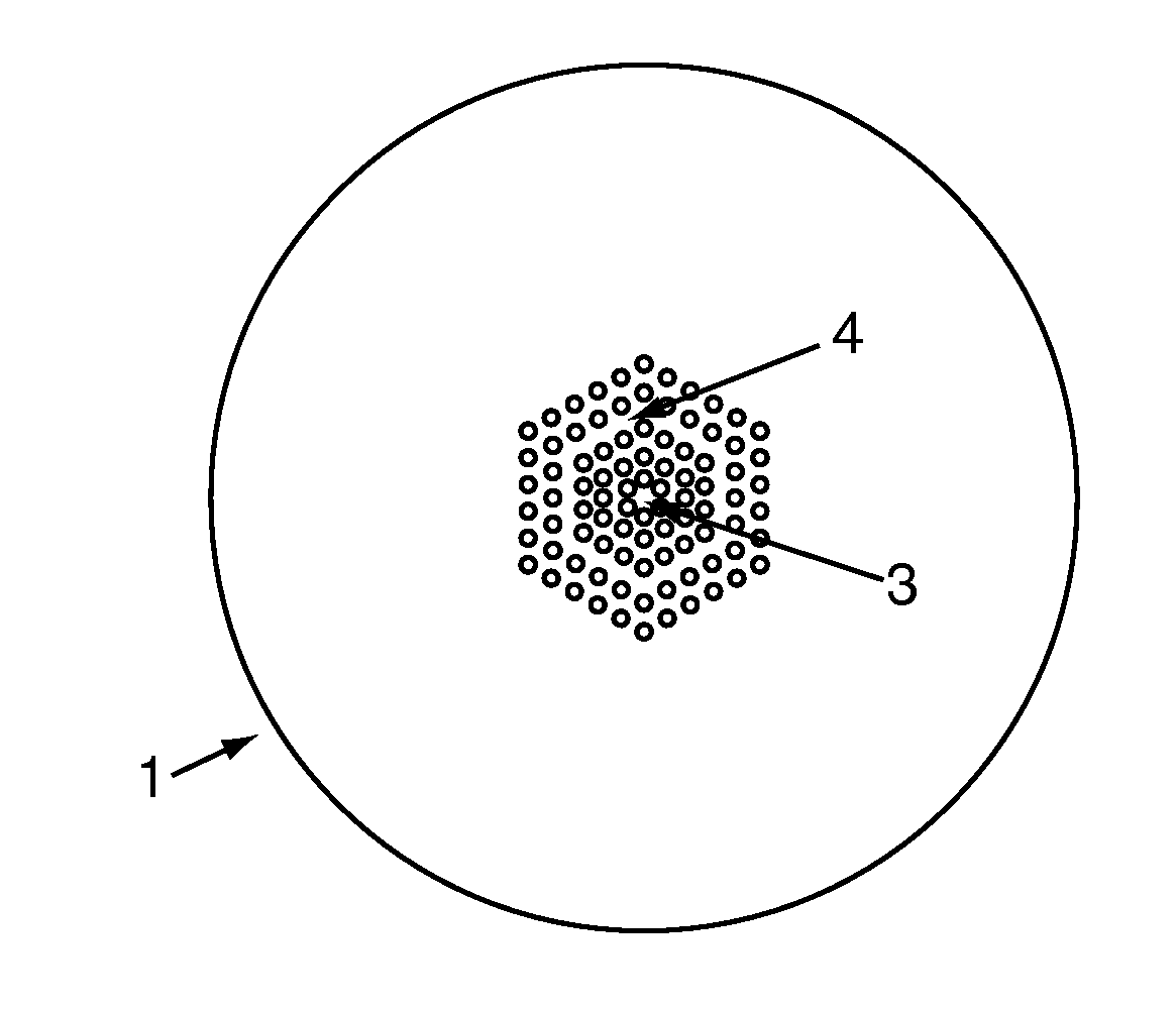
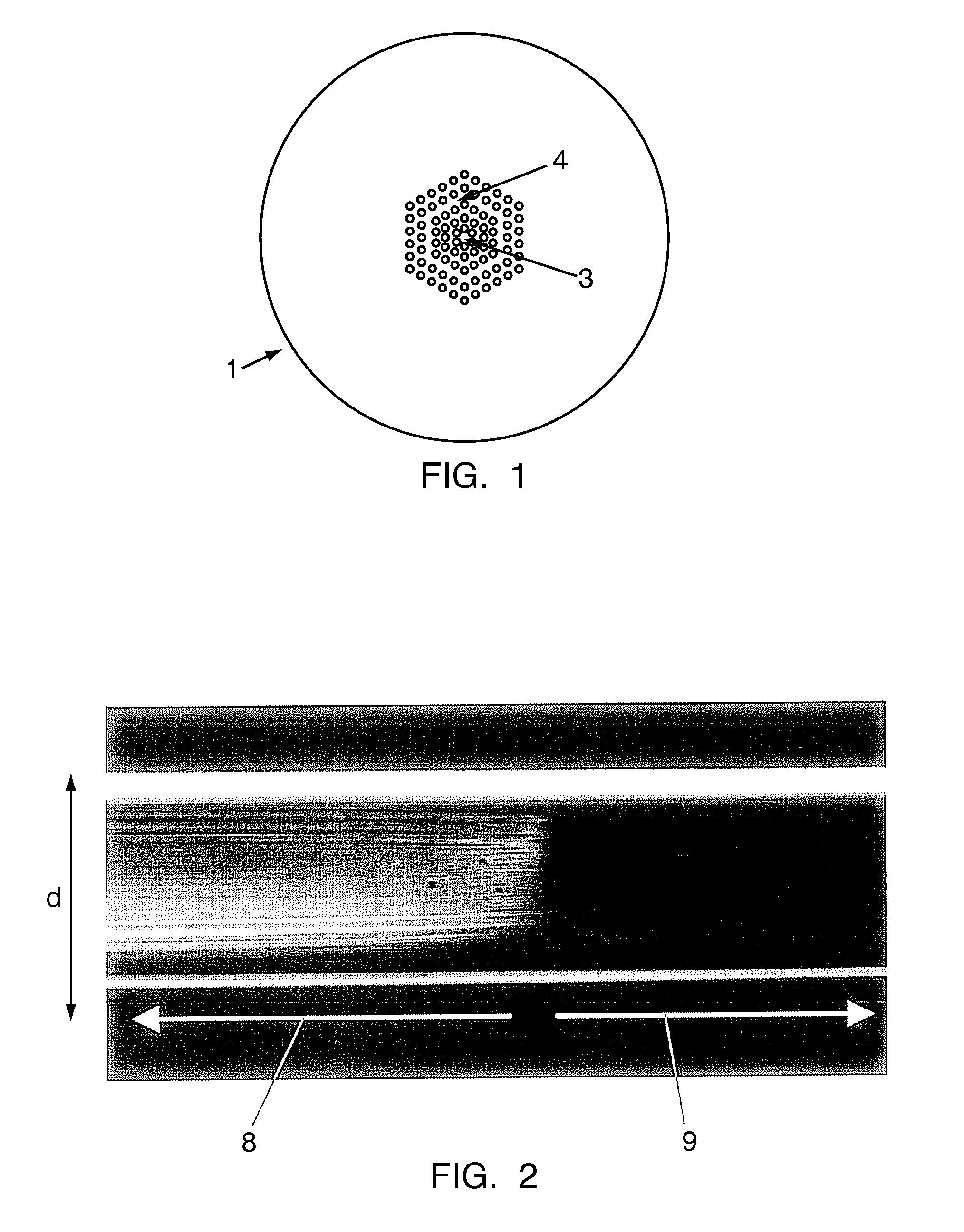
[0041]For the construction of a micro-structured Mach-Zehnder interferometer, an index-guiding micro-structured optical fiber (1) is used, consisting of a solid core (3) surrounded by rings of air holes (4), which can be arranged in a hexagonal pattern, as shown in FIG. 1. For example, it is possible to use commercially available MOF with a core of 11 μm in diameter, voids with average diameter of 2.7 μm, and the average separation between the voids of 5.45 μm. The fiber has an outer diameter of 125 μm. This type of MOF guides light by the modified total internal reflection principle. This index-guiding fiber is single mode from 620 nm to 1600 nm.

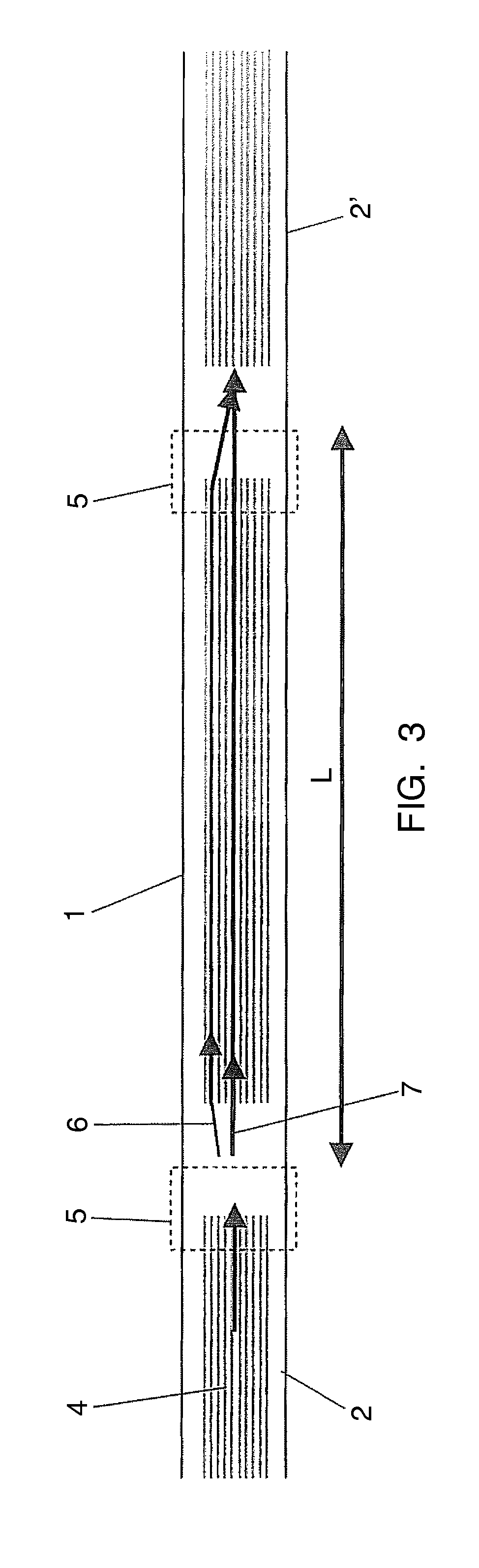
[0042]This all-MOF interferometer comprises two splices (5) in which the air holes (4) determining the holey region (8) of the MOF are fully collapsed, as shown in FIG. 2. The length of the collapsed region (9) in each splice (5) is about 300 micrometers. The collapsing of the air holes (4) makes the propagating light-beam to broaden, allow...


PUM

PropertyMeasurementUnit
lengthaaaaaaaaaa
wavelength rangeaaaaaaaaaa
central wavelengthaaaaaaaaaa

Abstract

A compact and stable interferometer is easily built only with fusion splices. The air-holes of a microstructured fiber are intentionally collapsed in the vicinity of the splices and this broadens the propagating optical mode, allowing coupling from core to cladding modes. The transmission spectrum is sinusoidal and of single frequency, indicating predominant interference between the fundamental core mode (7) and a cladding mode (6). A regular interference spectrum can be observed from 650 nm to 1600 nm with fringe visibility reaching 80%. The fringe spacing is inversely proportional to the distance between the splices. This behaviour has a significant impact in optical sensing and communications and so the interferometer can be applied for strain sensing. The device comprises two splices (5) of a microstructured optical fiber (1), said splices (5) determining two regions in which the air-holes (4) are collapsed, separated a length (L) along which said two modes are excited.

Description

FIELD OF THE INVENTION[0001]The present invention relates in general to manufacturing of optical fibre based devices and, more particularly, to an interferometer based on micro-structured optical fibers that can be used in a sensor element applicable for measuring diverse physical parameters, which are translated into output interference changes.STATE OF THE ART[0002]In optics, all-fiber interferometers are important devices since they are useful in diverse applications; ultrahigh-resolution metrology and light modulation are just two examples. Fiber interferometers can also be key devices in modern instruments such as gyroscopes.[0003]Numerous different approaches have been proposed to construct interferometers with conventional optical fibers.[0004]The advent of the so-called micro-structured optical fibers (MOFs) opens many other alternatives to construct interferometers that can be very useful for wide application areas.[0005]A micro-structured optical fiber (MOF), also known as...

Claims


Application Information

Patent Timeline
Patent Type & Authority Applications(United States)
IPC IPC(8): G01B9/02G02B6/255B23P11/00
CPCG02B6/02338G02B6/02376Y10T29/49826G02B6/29352G01B9/02049G02B6/2551G01B9/02041G02B6/255G02B6/28
Inventor VILLATORO, AGUSTIN JOELPRUNERI, VALERIOBADENES, GONCAL
Owner INST DE CIENCIAS FOTONICAS
Why Eureka
Try Eureka