Electric fan with water atomizer

a technology of electric fans and water atomizers, which is applied in the field of electric fans, can solve the problems of heavy and expensive electric fans b>1/b>

Inactive Publication Date: 2010-10-28
YUNG HSING ELECTRIC WORKS
View PDF6 Cites 14 Cited by
  • Summary
  • Abstract
  • Description
  • Claims
  • Application Information

AI Technical Summary

Benefits of technology

[0006]The primary objective of the present invention is to provide an electric fa

Problems solved by technology

The tank 7 and the pump 8 make the el

Method used


Image

  • Electric fan with water atomizer
  • Electric fan with water atomizer
  • Electric fan with water atomizer

Examples


Embodiment Construction

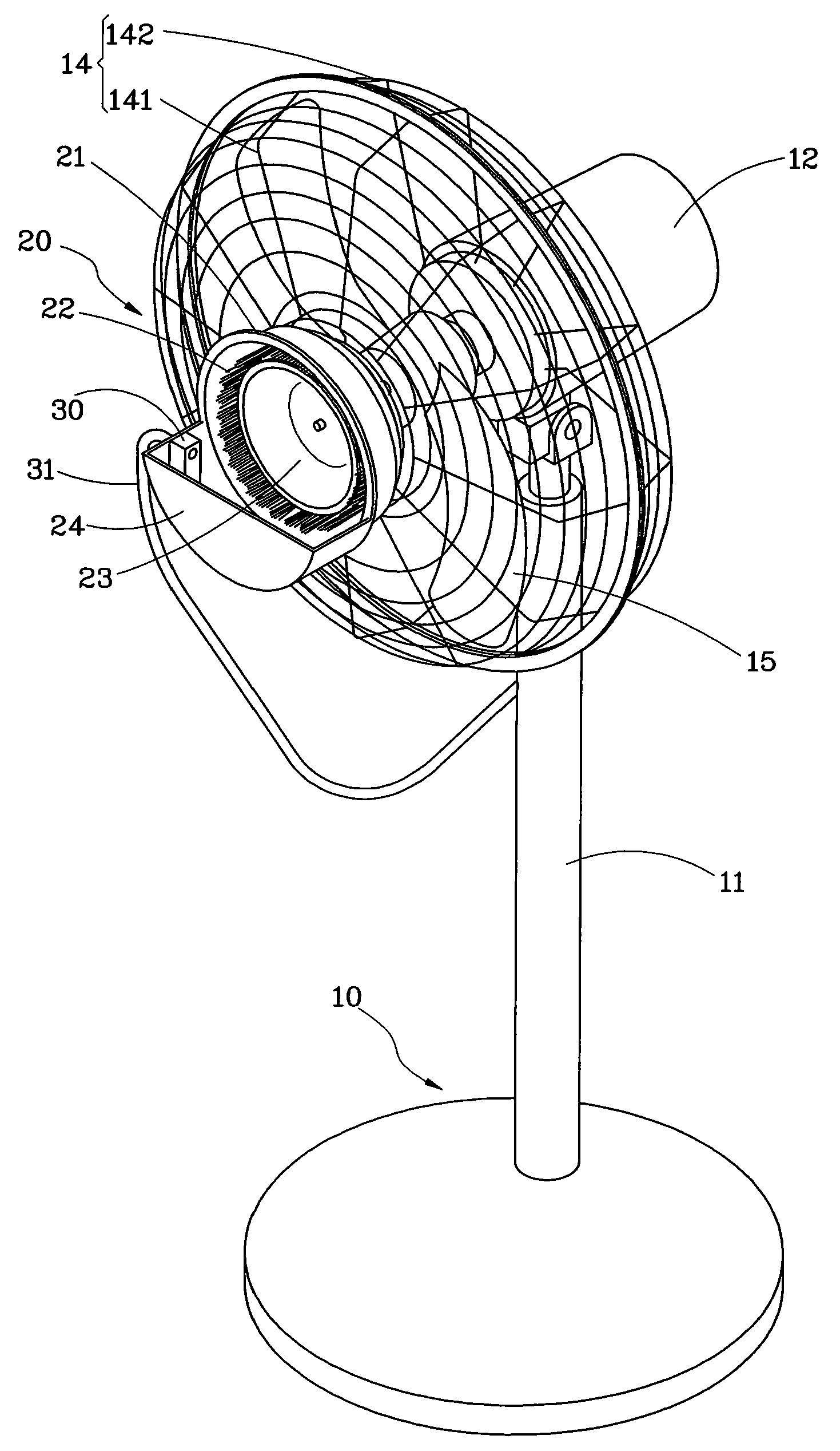
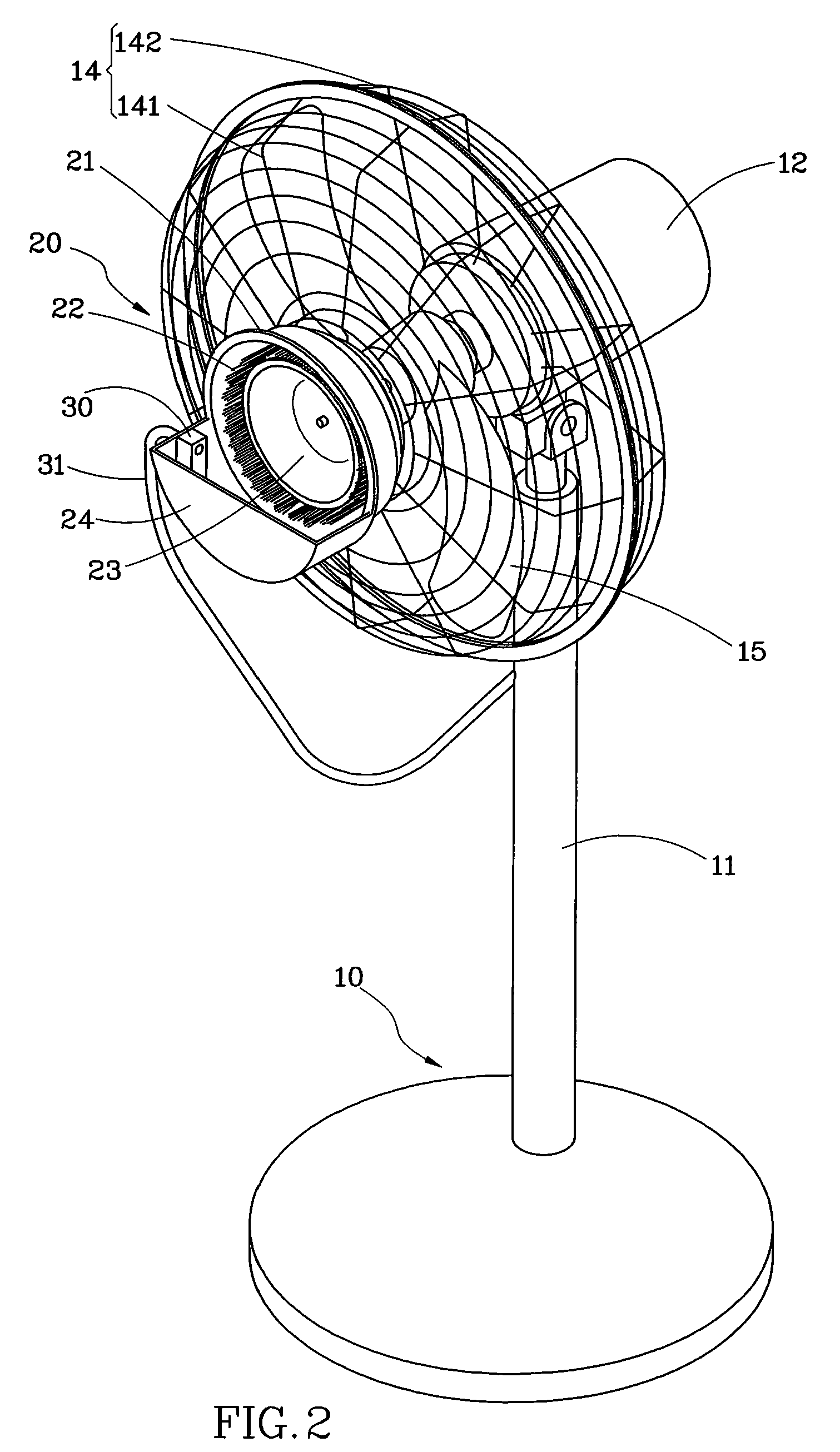
[0011]As shown in FIG. 2 and FIG. 3, an electric fan 10 has a stand 11, a case 12 on a top of the stand II, a motor 13 received in the case 12, a web 14, including a front web 141 and a rear web 142, fixed to the case 12, an a fan blade 15 within the web 14 and connected to the motor 13. An atomizer 20 is fixed to the front web 141.

[0012]The atomizer 20 includes a cup-like base member 21 fixed to the front web 141. A water impact fence 22 fixed to a front of the base member 21. The water impact fence 22 is a web like member. A rotary member 23 is provided with the water impact fence 22. Aforesaid elements are as same as the conventional devices, and the following is the new design of the present invention:

[0013]A gear box 25 is mounted on a back of the base member 21 and is connected to the rotary member 23. A flexible transmission member 26 connects the gear box 25 and the motor 13 of the electric fan 10 that the motor 13 may rotate the rotary member 23.

[0014]The base member 21 has...


PUM


Abstract

The present invention provides an electric fan with an atomizer. The electric fan includes a stand, a motor, a web, a fan blade within the web and connected to the motor. The water atomizer includes a base member mounted on a front of the web, a rotary member on a front of the base member, a water impact fence surrounding the rotary member, a gear box on a back of the base member and connected to the rotary member, a flexible transmission member connected to the gear box and the motor of the electric fan that the rotary member is driven by the motor, and a water container receiving water therein that the rotary member has at least a portion sinking in the water of the water container.

Description

BACKGROUND OF THE INVENTION[0001]1. Field of the Invention[0002]The present invention relates generally to an electric fan, and more particularly to an electric fan with a water atomizer.[0003]2. Description of the Related Art[0004]FIG. 1 shows a conventional electric fan I equipped with a water atomizer 2 on a front web thereof. The water atomizer 2 includes a cup-like member 3, a circular web 4 on the member 3, and a rotary member 5 within the web 4. The rotary member is driven by a motor 6 on a back of the member 3 to sputter water to the web 4 for water atomization, and the electric fan I will blow the atomized water out to enhance the cooling capacity.[0005]A desired speed of the rotary member 5 is different from the electric fan 1 that such electric fan 1 usually has two motors, one for the electric fan 1 and one for the water atomizer 2. Besides, such electric fan 1 has a tank 7 on a base thereof, and a pump 8 in the tank 7 to pump water to the water atomizer 2. The tank 7 an...

Claims


Application Information

Patent Timeline
IPC IPC(8): B05B3/02B67D5/44B05B9/04
CPCB05B3/10B05B12/081F04D29/705Y02B30/545F24F6/14F24F7/007F24F5/0035Y02B30/54
Inventor LIN, JUNG-HUA
Owner YUNG HSING ELECTRIC WORKS
Why Eureka
Try Eureka