Apparatus and method for sequentially anchoring multiple graft ligaments in a bone tunnel

a technology of graft ligaments and sequential anchoring, which is applied in the direction of screws, ligaments, prostheses, etc., can solve the problems of inconvenient operation, inconvenient maintenance, and inability to drill two tunnels in close proximity

Active Publication Date: 2010-10-28
THE CLEVELAND CLINIC FOUND
View PDF27 Cites 47 Cited by
  • Summary
  • Abstract
  • Description
  • Claims
  • Application Information

AI Technical Summary

Problems solved by technology

In many cases, ligaments are torn or ruptured as a result of trauma.
However, a single-graft reconstruction does not reflect the original knee structure and therefore might lead to future adverse effects due to long-term use of the knee in a mechanically different configuration than the native anatomy.
However, drilling two tunnels in close proximity is technically difficult and brings about a heightened risk of complication.
Due to the limited confines of the bone tunnels, traditional graft-anchoring techniques may not be effective in placing dual graft ligaments within a single tunne...

Method used


Image

  • Apparatus and method for sequentially anchoring multiple graft ligaments in a bone tunnel
  • Apparatus and method for sequentially anchoring multiple graft ligaments in a bone tunnel
  • Apparatus and method for sequentially anchoring multiple graft ligaments in a bone tunnel

Examples


first embodiment

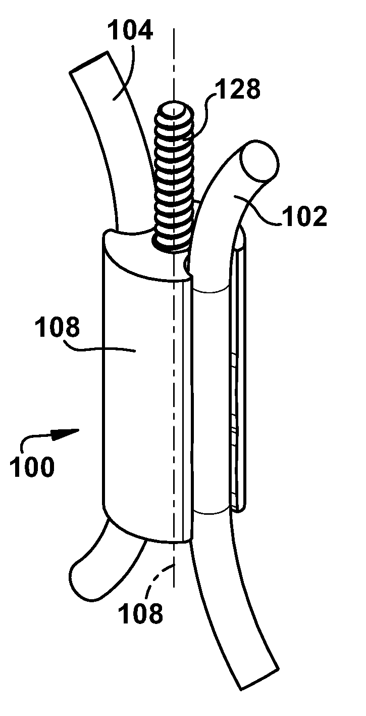
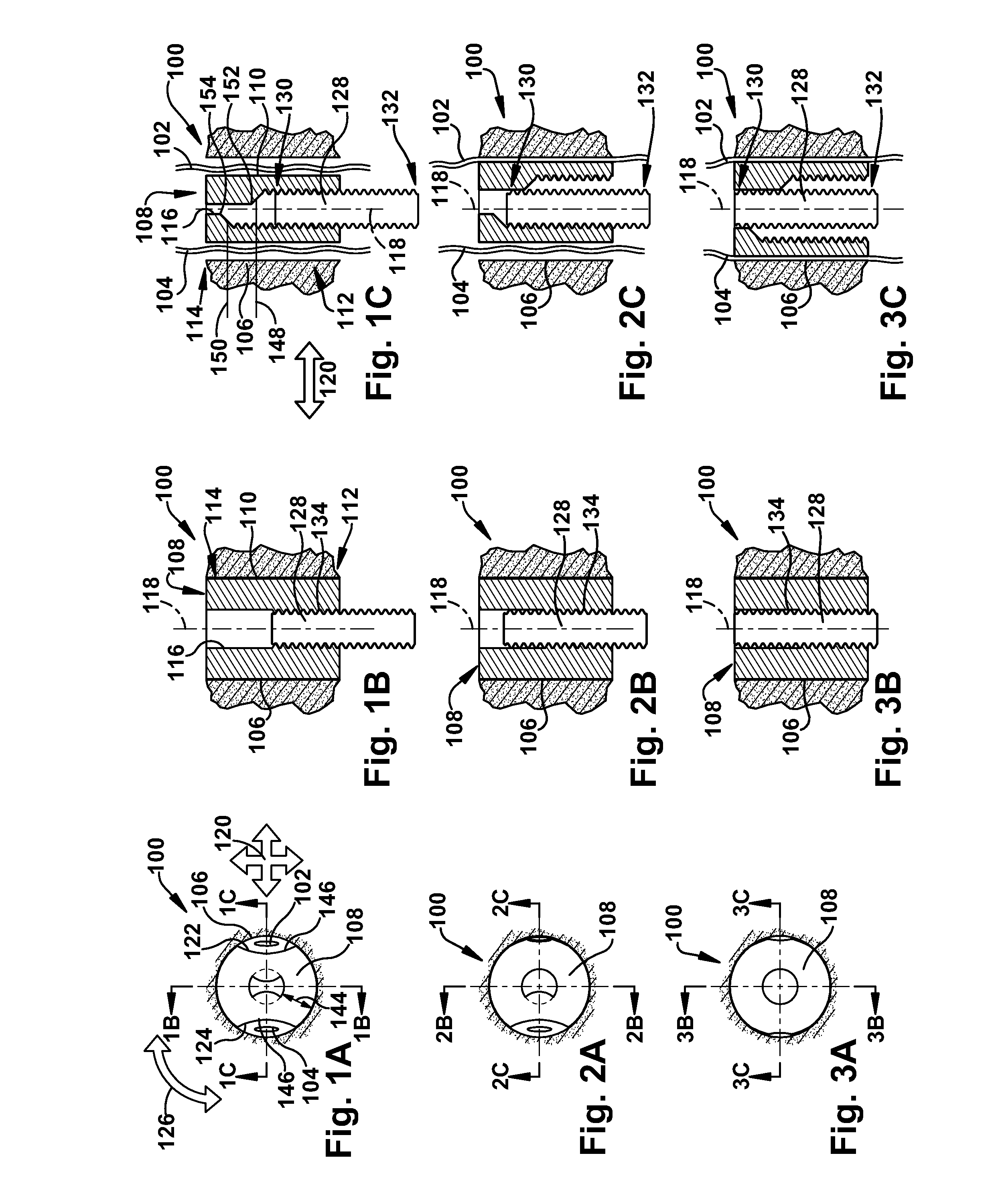
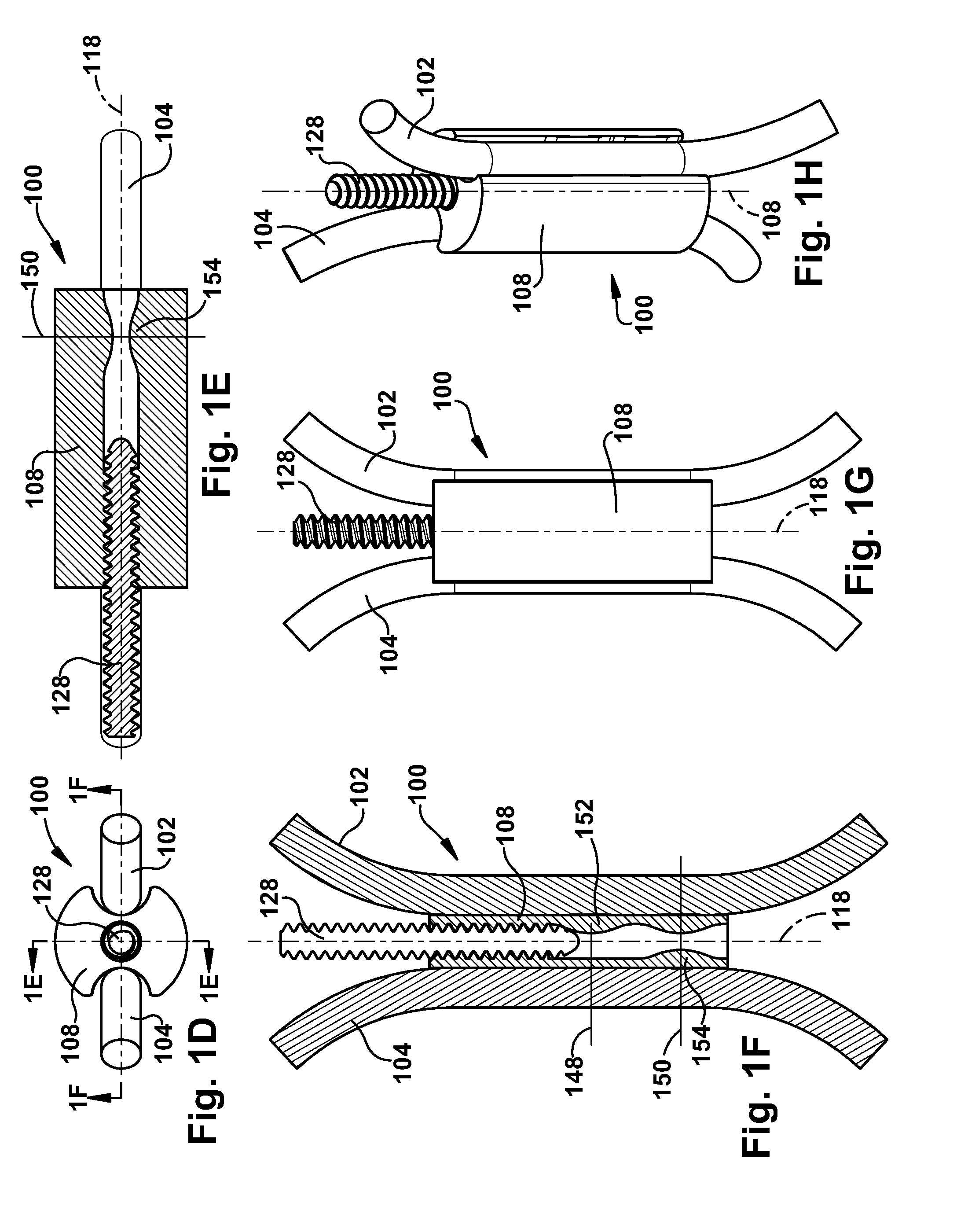
[0039]In accordance with the present invention, FIGS. 1A, 1B, 10, 2A, 2B, 2C, 3A, 3B, and 3C schematically depict an apparatus 100 for anchoring at least two graft ligaments 102 and 104 within a longitudinal bone tunnel 106. More specifically, the apparatus 100 can be a sequentially-actuated graft anchor system 100 for use in anchoring at least two longitudinally extending graft ligaments 102 and 104 within a bone tunnel 106 during replacement of a native anterior cruciate ligament (“ACL”), and will be discussed as such herein. However, one of ordinary skill in the art will recognize that the apparatus 100 may be useful for sequentially anchoring any plurality of elongate strands within an aperture. For example, the apparatus 100 may be used to anchor a plurality of longitudinally extending graft ligaments within a bone tunnel during replacement of a native posterior cruciate ligament.

[0040]A longitudinal sleeve 108 has a sleeve outer surface 110 and longitudinally separated proxima...

second embodiment

[0054]In the embodiment of FIGS. 1A-3C, a substantially straight-sided actuating member 128 interacts with an asymmetrically offset profile on the sleeve inner lumen 116. In contrast, FIGS. 7A-9B schematically depict an apparatus 100b according to the present invention.

[0055]The apparatus 100b of FIGS. 7A-9B is similar to the apparatus 100 of FIGS. 1A-3C and therefore, structures of FIGS. 7A-9B that are the same as or similar to those described with reference to FIGS. 1A-3C have the same reference numbers with the addition of the suffix “a”. Description of common elements and operation similar to those in the previously described first embodiment will not be repeated with respect to the second embodiment. In the embodiment of FIGS. 7A-9B, the sleeve 108 is more rigid than in the previously described embodiment and the asymmetrically offset profile is on the actuating member outer surface 134b. Accordingly, the first and second engagement thresholds 148b and 150b are defined by first...


PUM


Abstract

An apparatus for anchoring at least two graft ligaments within a longitudinal bone tunnel includes a longitudinal sleeve having at least two radially spaced ligament-contacting surfaces located in lateral opposition to a sleeve inner lumen. The sleeve is configured for at least partial insertion into the bone tunnel with each graft ligament positioned laterally adjacent a different ligament-contacting surface. The graft ligaments are at least partially located between the bone tunnel and the sleeve. An actuating member has longitudinally separated proximal and distal actuating member ends. An asymmetrically offset profile is defined by at least one of the sleeve and the actuating member. The asymmetrically offset profile has a plurality of longitudinally spaced engagement thresholds. The actuating member is inserted longitudinally into the sleeve to cause frictional engagement of each graft ligament with both the bone tunnel and at least one ligament-contacting surface. The frictional engagement of each graft ligament is temporally spaced apart from the frictional engagement of at least one other graft ligament. The temporal spacing is provided by the plurality of engagement thresholds. A method of anchoring at least two longitudinally extending graft ligaments within a bone tunnel is also provided.

Description

RELATED APPLICATION [0001]This application claims priority from U.S. Provisional Application No. 61 / 171,518, filed Apr. 22, 2009, the subject matter of which is incorporated herein by reference.TECHNICAL FIELD [0002]The present invention relates to an apparatus and method for anchoring graft ligaments and, more particularly, to an apparatus and method for sequentially anchoring multiple graft ligaments in a bone tunnel.BACKGROUND OF THE INVENTION[0003]Ligaments are tough bands of tissue which serve to connect the articular extremities of bones, or to support or retain organs in place within the body. Ligaments are typically composed of coarse bundles of dense fibrous tissue which are disposed in a parallel or closely interlaced manner, with the fibrous tissue being pliant and flexible, but not significantly extensible.[0004]In many cases, ligaments are torn or ruptured as a result of trauma. As a result, various procedures have been developed to repair or replace such damaged ligame...

Claims


Application Information

Patent Timeline
IPC IPC(8): A61F2/08
CPCA61B2017/0425A61B2017/0438A61F2/0811A61F2002/0882A61F2002/0852A61F2002/0858A61F2002/0835Y10T292/1099
Inventor FENING, STEPHEN D.MINIACI, ANTHONY
Owner THE CLEVELAND CLINIC FOUND
Why Eureka
Try Eureka