Control system, operation device and control method

a control system and operation device technology, applied in multi-programming arrangements, instruments, computing, etc., can solve the problems of not improving the operability and usability the limited range of self-motion, and the inability to self-propelled functions for outputting information from the information processing apparatus work, etc., to achieve the effect of improving the convenience of the information processing apparatus

Inactive Publication Date: 2010-10-28
SONY CORP
View PDF3 Cites 119 Cited by
  • Summary
  • Abstract
  • Description
  • Claims
  • Application Information

AI Technical Summary

Benefits of technology

The present invention provides a control system that can improve the efficiency of an information processing machine by automatically adjusting the status of its peripherals based on their usage with the main machine. This makes it easier for users to access and utilize the features of the information processing machine without having to manually change settings or switch between devices.

Problems solved by technology

This patent discusses how various processes and tasks can be done using a computer connected to the internet. To make these activities easier, different types of peripherals like mice and keyboards are available to work with the computer. However, sometimes wires get in between the mouse and the computer, making it difficult to operate. So, this patent introduces a wireless mouse that solves this problem. Additionally, some mices even have their own movement system based on instructions from the computer - they're called self-propelled mices. These mices can help output information from the computer while also being moved around.

Method used


Image

  • Control system, operation device and control method
  • Control system, operation device and control method
  • Control system, operation device and control method

Examples


first embodiment

[(1) System Configuration Example]

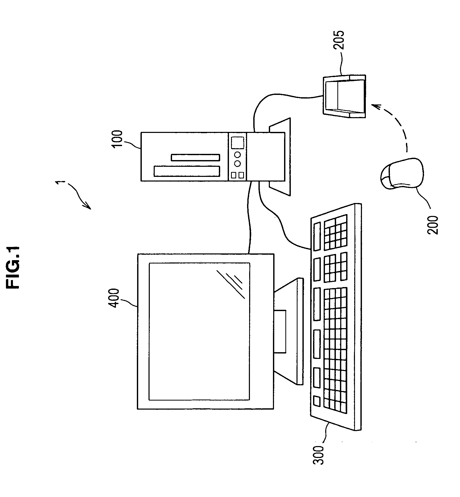
[0032]First, a schematic configuration of a control system according to a first embodiment of the present invention will be described based on FIG. 1. In addition, FIG. 1 is an explanatory diagram showing a configuration of a control system 1 according to the present embodiment.

[0033]The control system 1 according to the present embodiment includes an information processing apparatus 100 which is, for example, a personal computer, and a mouse 200, a keyboard 300 and a display 400 which are external devices communicably connected to the information processing apparatus 100, as shown in FIG.1. The information processing apparatus 100 includes a processing unit capable of executing an application and is connected with an input device such as the mouse 200 and the keyboard 300 in order to operate the information processing apparatus 100. Moreover, the information processing apparatus 100 is connected to an output device such as the display 400 and a spe...

second embodiment

2. Second Embodiment

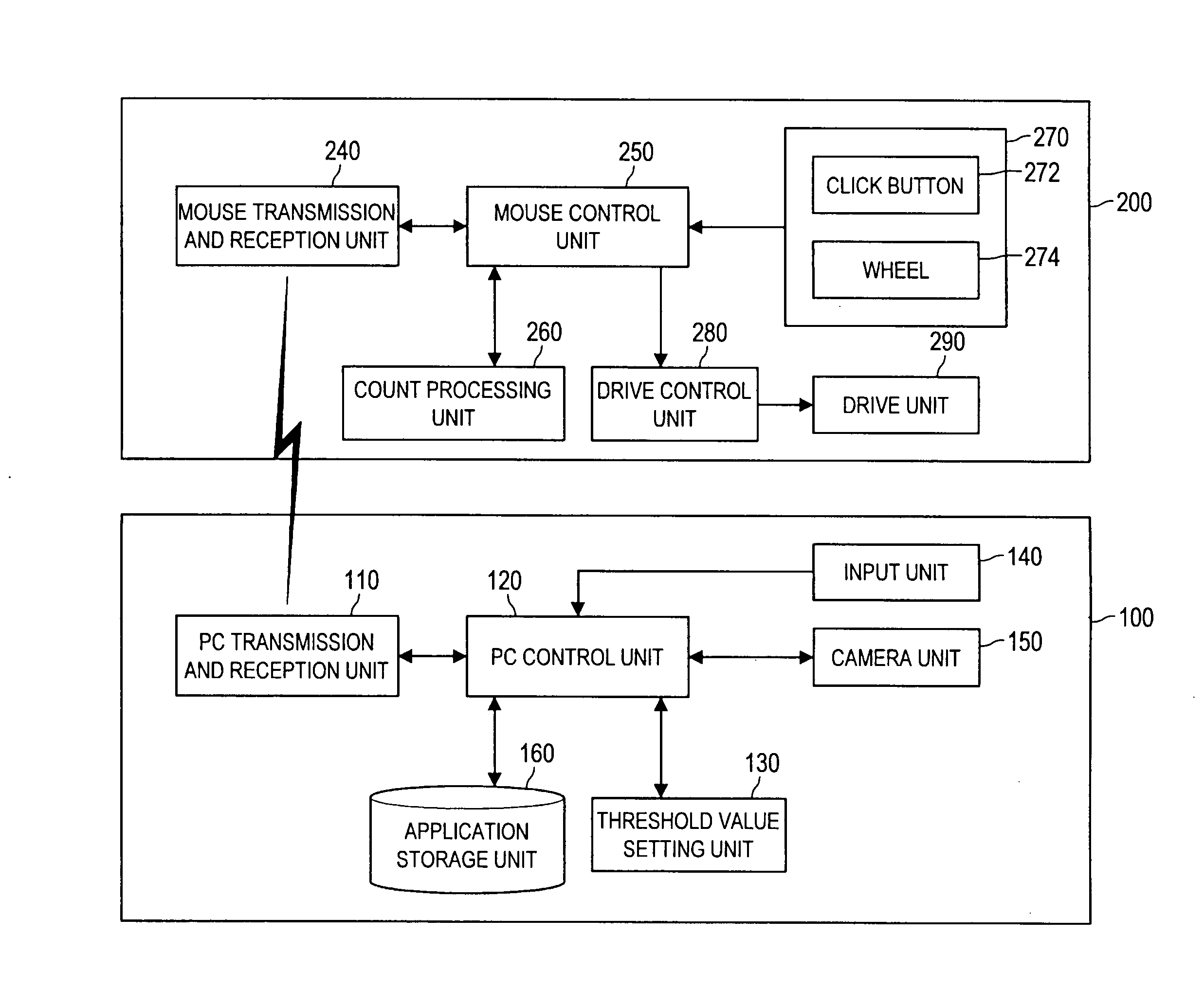
[0096]Next, a second embodiment of the present invention will be described based on FIG. 9. In the present embodiment, there will be described a control system configured by connecting an information processing apparatus 310 capable of executing an application and an external device 320 which functions in connection with the information processing apparatus 310, in a manner that they can communicate with each other. The present embodiment is a variation of the control system 1 including the information processing apparatus 100 such as a personal computer and the mouse 200 shown in the first embodiment, and is an example of applying the control system 1 to devices other than the information processing apparatus 100 and the mouse 200. In the following, a configuration of a control system according to the present embodiment and its operation will be described. In addition, FIG. 9 is a block diagram showing functional configurations of devices constituting the contro...


PUM


Abstract

There is provided an information processing apparatus including an execution unit for executing an application, a threshold value setting unit for setting, according to the running application, a threshold value which determines a timing of changing an operational state of the external device, a first detection unit for detecting an input signal, and a first transmission and reception unit for exchanging information with an external device. Moreover, there is provided the external device including a second transmission and reception unit for exchanging information with the information processing apparatus, a second detection unit for detecting an input signal, a determination unit for determining whether or not to change the operational state of the external device from the threshold value based on the detection result, and a change processing unit for changing the operational state of the external device based on the determination result.

Description


Claims


Application Information

Patent Timeline
Owner SONY CORP
Why Eureka
Try Eureka