
Control apparatus and control method therefor

a control apparatus and control method technology, applied in the direction of memory address/allocation/relocation, instruments, computing, etc., can solve the problems of large load on the cpu, incomplete deletion of data, and increase the complexity of configuration

Inactive Publication Date: 2010-10-28
CANON KK
View PDF8 Cites 17 Cited by
  • Summary
  • Abstract
  • Description
  • Claims
  • Application Information

AI Technical Summary

Benefits of technology

[0014]According to an aspect of the present invention, an apparatus includes a receiving unit configured to receive a command for controlling at least one of a plurality of storage apparatuses from a host apparatus, a sending unit configured to send overwrite data configured to overwrite a region storing data to a specific storage apparatus, when the received command is a deletion command to delete the stored data, and a control unit configured to store the received command at lea

Problems solved by technology

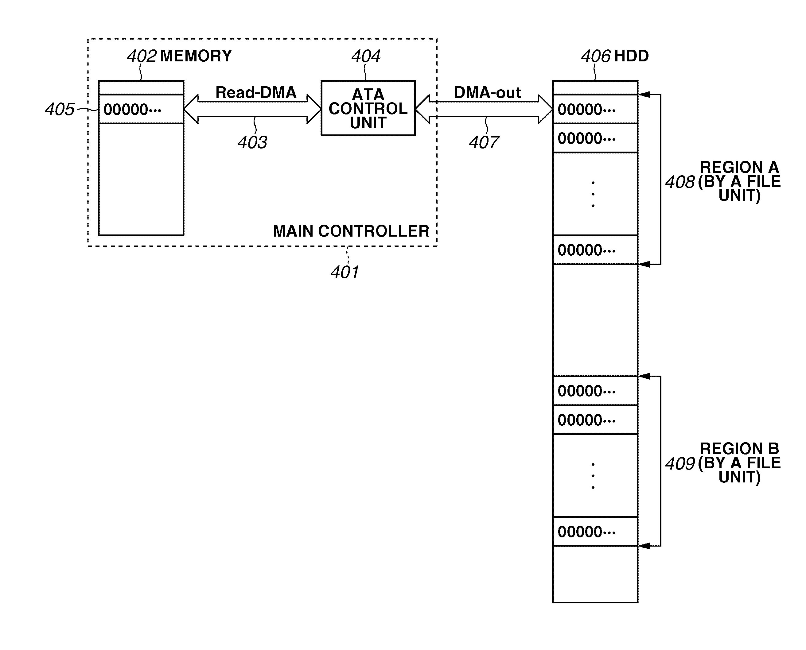
However, it is increasingly common to completely delete data using a process of overwriting the files on a predetermined number of times with specific pattern data in addition to deletion of file management data in the hard disk apparatus.
However, when the size of the file to be deleted by overwriting is extremely large or when a consecutive region on the memory cannot be ensured, a large load is placed on the CPU by use of an inefficient method in which the above process is repeated many times.
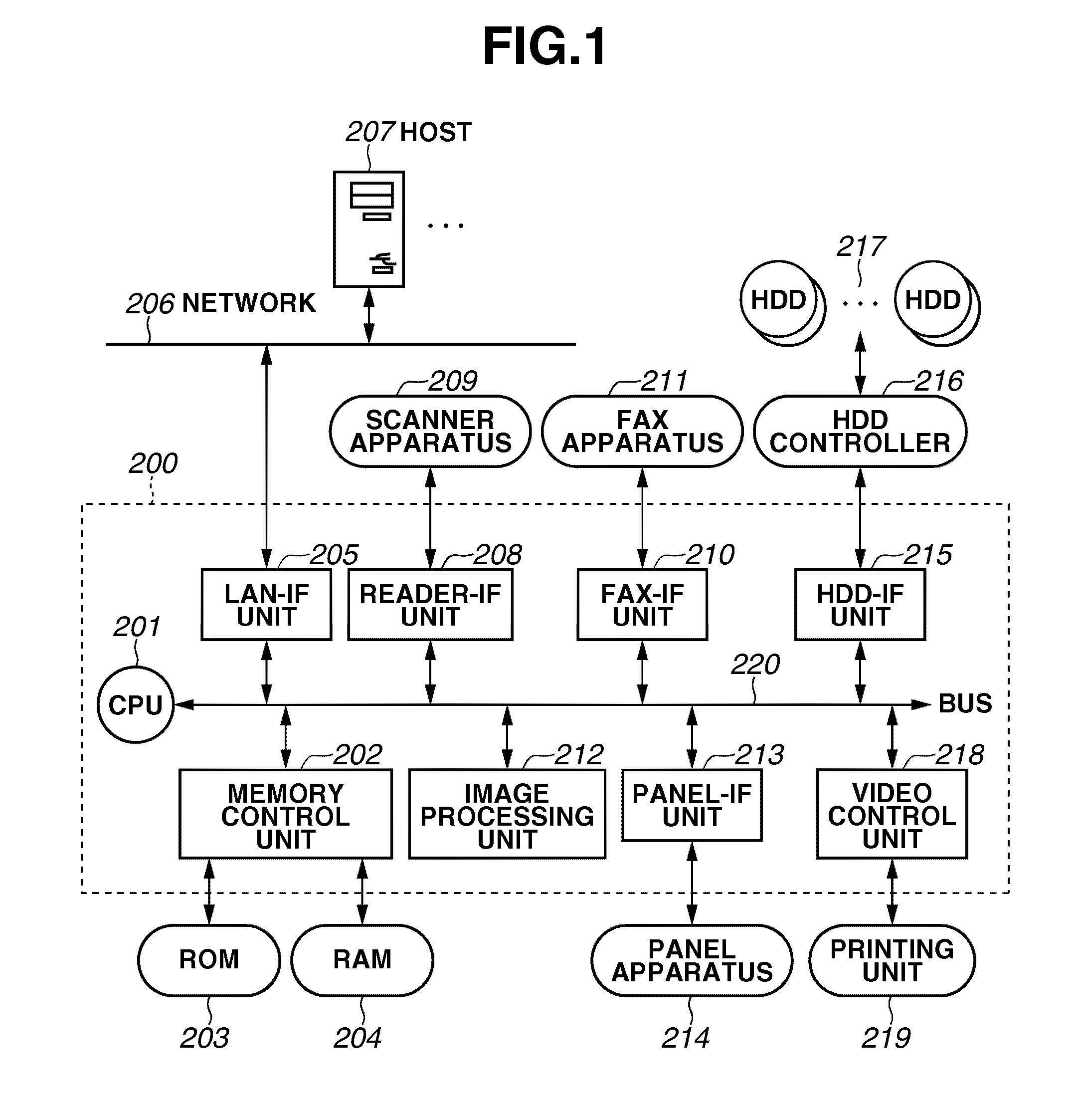
In recent built-in apparatuses such as printers, complexity of the configuration is increased, and often they are configured by a plurality of OS.
Furthermore, since the hard disk controller is to rewrite the file management information, when a mirroring system is configured using a plurality of hard disks, control operations are complicated because the same management information for a plurality of objects is to be updated.
Consequently, there are difficulties for application of the method, which is discussed in Japanese Patent Application Laid-Open No. 2005-346306, to a wide range of system configurations.

Method used


Image

  • Control apparatus and control method therefor
  • Control apparatus and control method therefor
  • Control apparatus and control method therefor

Examples


Embodiment Construction

[0031]Various exemplary embodiments, features, and aspects of the invention will be described in detail below with reference to the drawings.

[0032]Elements of one embodiment may be implemented by hardware, firmware, software, or any combination thereof. The term hardware generally refers to an element having a physical structure such as electronic, electromagnetic, optical, electro-optical, and mechanical, electro-mechanical parts, etc. A hardware implementation may include analog or digital circuits, devices, processors, applications specific integrated circuits (ASICs), programmable logic devices (PLDs), field programmable gate arrays (FPGAs), or any electronic devices. The term software generally refers to a logical structure, a method, a procedure, a program, a routine, a process, an algorithm, a formula, a function, an expression, etc. The term firmware generally refers to a logical structure, a method, a procedure, a program, a routine, a process, an algorithm, a formula, a fu...


PUM


Abstract

When a controller receives a new command from a main controller during overwrite-deletion processing for a specific storage apparatus, the received command is stored at least until completion of the overwrite-deletion processing when the received command is a command to the specific storage apparatus. Alternatively, progression of overwrite-deletion process is stored and priority processing of the received command is executed. On the other hand, when the received command is not a command to the specific storage apparatus, processing for the command is executed.

Description

BACKGROUND OF THE INVENTION[0001]1. Field of the Invention[0002]The present invention relates to a control apparatus and a control method for the control apparatus.[0003]2. Description of the Related Art[0004]Conventionally, when discarding a storage apparatus such as a hard disk apparatus (hereinafter a hard disk apparatus is used as an example of a storage apparatus) mounted, for example, in a personal computer (PC) or a printer, data in the hard disk apparatus is deleted to prevent leakage of confidential data. However, it is increasingly common to completely delete data using a process of overwriting the files on a predetermined number of times with specific pattern data in addition to deletion of file management data in the hard disk apparatus.[0005]Recently, enhanced security awareness has caused, other than when hard disks are discarded, a need for overwrite-deletion by a printing job unit of the operation region in the hard disk apparatus including intermediate data generate...

Claims


Application Information

Patent Timeline
IPC IPC(8): G06F12/00G06F3/00G06F21/60G06F21/80
CPCG06F21/85G06F2221/2143G06F12/02H04N2201/218H04N2201/0094
Inventor MATSUMOTO, AKIHIRO
Owner CANON KK
Learn More