
Proportional counterbalance system for mower cutting units

a technology of mower cutting unit and counterbalance system, which is applied in the field of mowers, can solve the problems of affecting the traction of the traction vehicle, and the counterbalance system was not designed to allow the traction vehicle to regain traction

Active Publication Date: 2010-11-04
TORO CO THE
View PDF9 Cites 16 Cited by
  • Summary
  • Abstract
  • Description
  • Claims
  • Application Information

AI Technical Summary

Benefits of technology

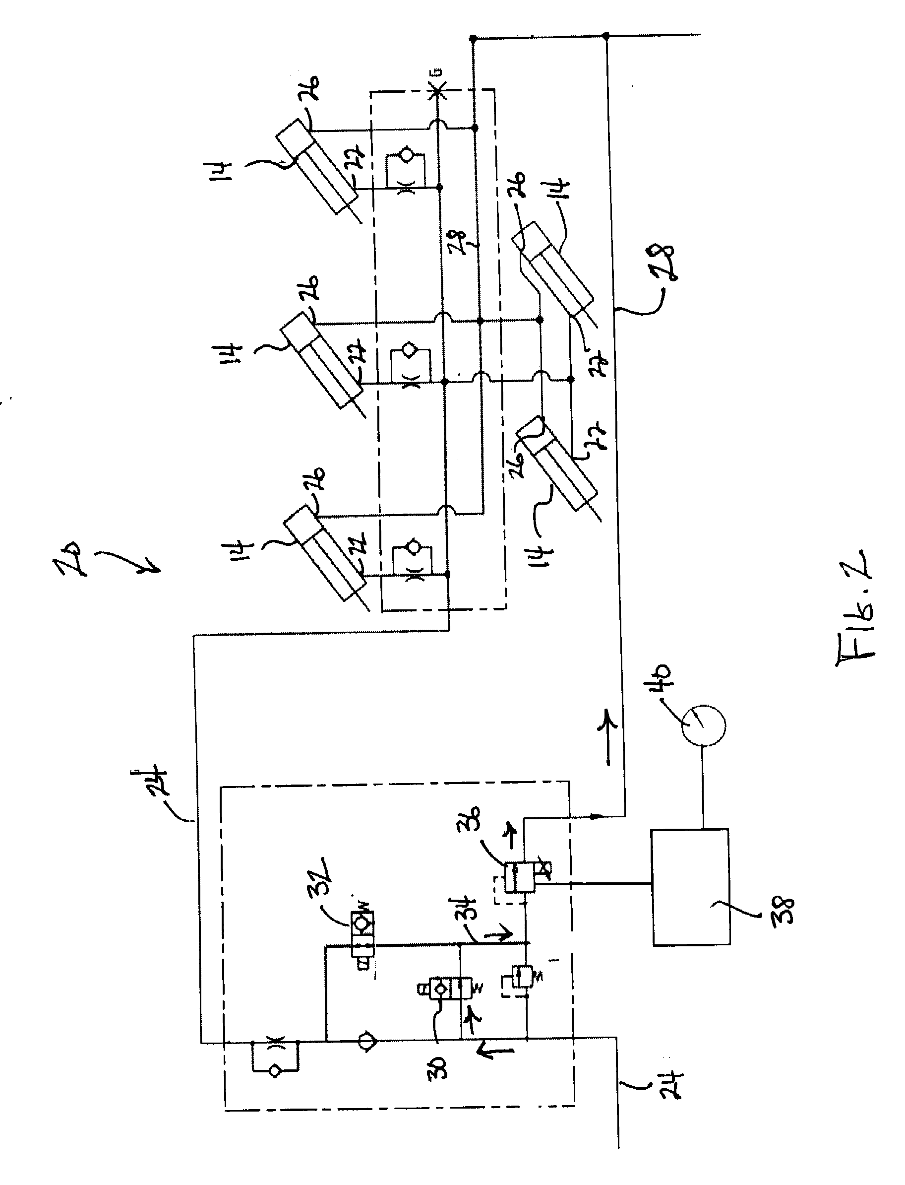
[0008]One aspect of this invention relates to a mower for cutting grass growing on a turf surface comprises a traction vehicle supported for rolling over the ground by a plurality of wheels. At least some of the wheels are powered by a traction drive system to propel the traction vehicle over the ground. A grass cutting unit is operatively connected to the traction vehicle. The grass cutting unit is supported in a mowing position such that at least some of the weight of the grass cutting unit is directly borne by the ground when the cutting unit is in the mowing position. A hydraulic cylinder is coupled to the cutting unit to lift the cutting unit out of engagement with the ground to place the cutting unit into a raised transport position out of engagement with the ground and to lower the cutting unit into engagement with the ground to place the cutting unit into the mowing position. A lift and lower hydraulic circuit is provided for the cylinder with the hydraulic circuit having a fluid supply circuit to the cylinder and a fluid return circuit from the cylinder. A counterbalance system is provided that is effective to shift desired amounts of the weight of the cutting unit between the ground and the traction vehicle. The counterbalance system comprises a proportional hydraulic valve positioned in the return circuit to generate a backpressure in the return circuit that counterbalances at least a portion of the weight of the cutting unit on the ground by shifting the portion of weight to the traction vehicle. The counterbalance system also includes an electronic controller operatively connected t

Problems solved by technology

It has also long been known in the mower art that this can adversely affect the traction of the traction vehicle.
Such an abrupt traction shift could potentially be distracting or alarming to the operator, particularly to an unskilled operator, and thus represented a disadvantage of the prior art system.
In addition, if the traction vehicle lost traction before the counterbalance system applied the higher backpressure, the counterbalance system was not designed to allow the traction vehicle to regain traction once traction was lost.

Method used


Image

  • Proportional counterbalance system for mower cutting units
  • Proportional counterbalance system for mower cutting units
  • Proportional counterbalance system for mower cutting units

Examples


Embodiment Construction

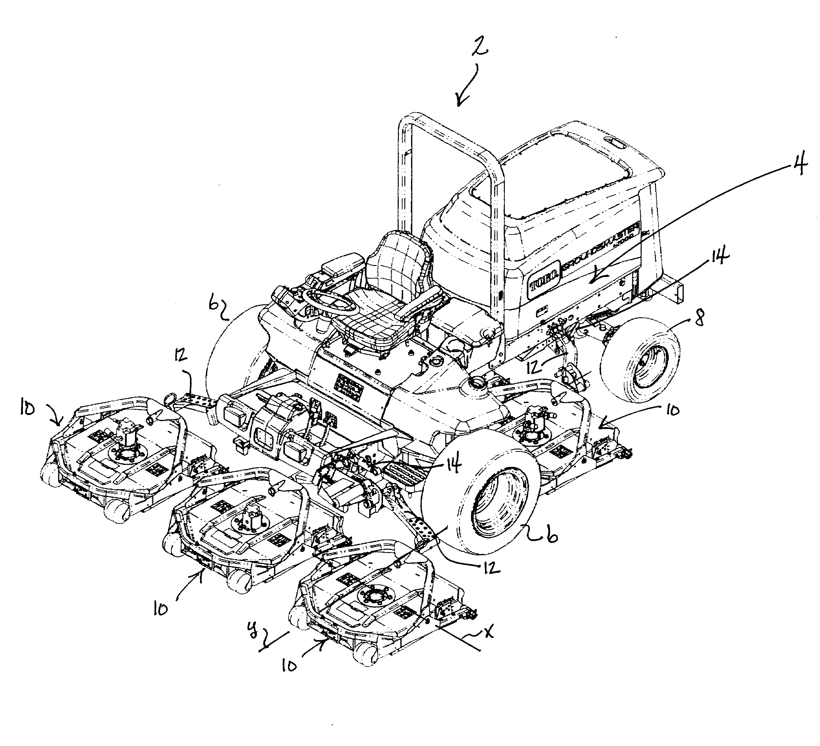
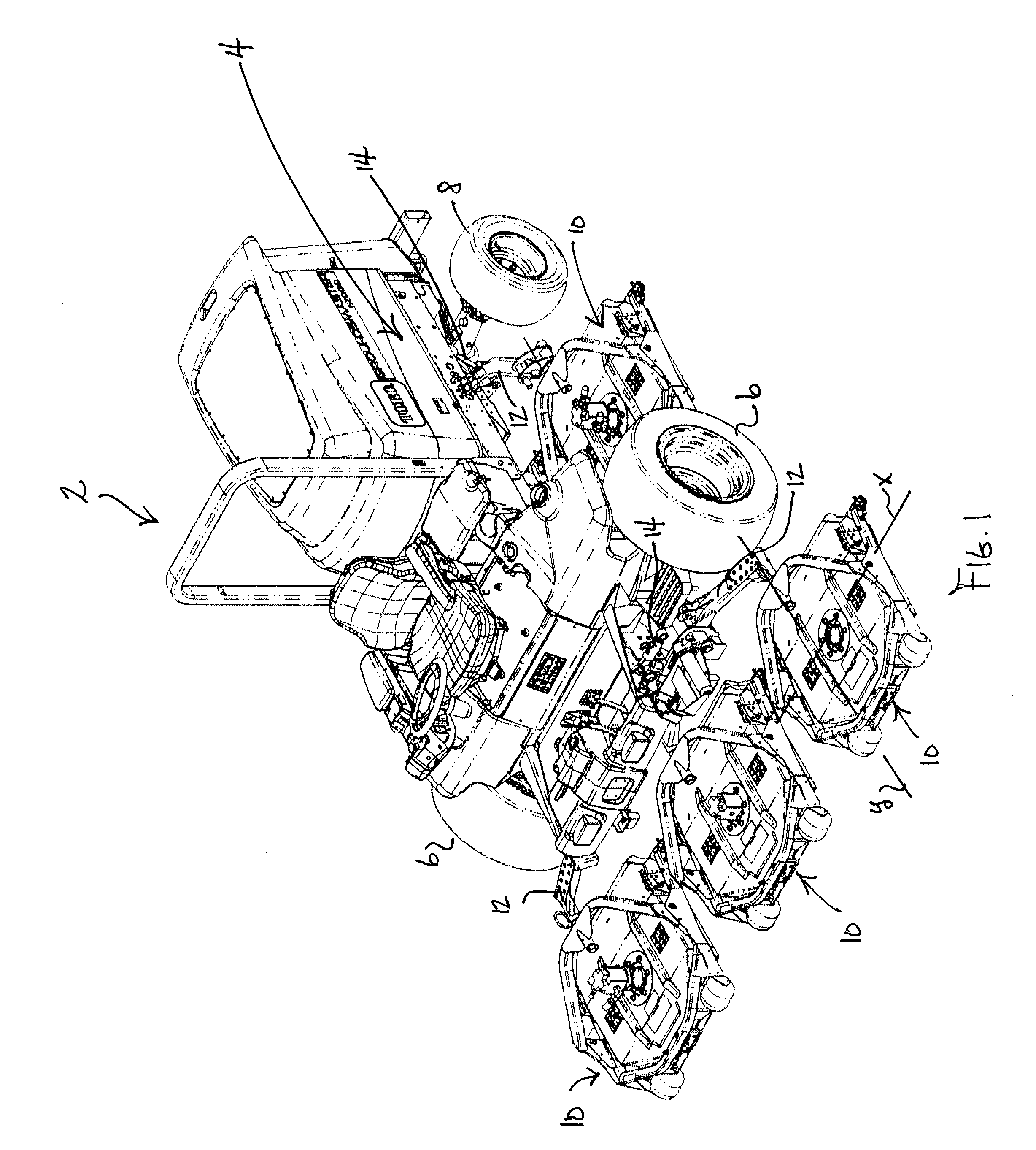
[0016]FIG. 1 is a view of one mower 2 with which the proportional counterbalance system of this invention may be used. Mower 2 depicted in FIG. 1 is a Toro Groundsmaster 4500-D, manufactured and sold by The Toro Company, the assignee of this invention. Mower 2 comprises a traction vehicle 4 having a pair of front drive wheels 6 and a pair of rear wheels 8. Rear wheels 8 may be driven in a 4WD drive mode but are not driven in a 2WD drive mode. Traction vehicle 4 carries five cutting units 10 in a 3-2 gang configuration comprising a front row of three cutting units followed by a rear row of two cutting units (only one of which can be seen in FIG. 1) that cover the gaps between cutting units 10 in the front row.

[0017]Cutting units 10 comprise rotary cutting decks but reel cutting units could be used in place of the depicted rotary cutting decks. The number of cutting units 10 can also vary and be larger or smaller than the five cutting units shown and cutting units 10 can be arranged i...


PUM


Abstract

A proportional counterbalance system comprises an electronic controller operatively connected to a proportional hydraulic control valve to substantially continuously and infinitely adjust the backpressure in a fluid return circuit from the lift and lower cylinders of a plurality of cutting units on a mower. The backpressure is infinitely adjusted within a band between a minimum and a maximum backpressure in concert with a varying input parameter to the controller to transfer desired amounts of weight of the cutting units from the ground to the traction vehicle of the mower to enhance traction as needed. A wide variety of input parameters can be used, including a selected operating condition of the mower, a selected environmental condition of the turf surface being mowed, the actual, real time location of the mower on the turf surface, altitude above sea level, and manual input from the operator.

Description

TECHNICAL FIELD[0001]This invention relates to a mower comprising a self propelled traction vehicle that carries and thereby propels at least one grass cutting unit. More particularly, this invention relates to such a mower in which the cutting units carried on the traction vehicle have their weight at least partially borne by the ground during mowing.BACKGROUND OF THE INVENTION[0002]Certain well known mowers have one or more grass cutting units operatively connected to a traction vehicle such that the motion of the traction vehicle propels the cutting units over the ground to cut grass. The cutting units can comprise reel cutting units with each cutting unit having a reel that rotates about a horizontal axis to sweep the grass against a sharpened bedknife to cut the grass by severing the grass between the reel and the bedknife. Alternatively, the cutting units can comprise rotary cutting decks with each cutting unit having a blade that rotates about a vertical axis to cut the grass...

Claims


Application Information

Patent Timeline
IPC IPC(8): A01D34/00
CPCA01D75/306A01D34/44A01B63/11
Inventor MOE, CHAD L.DRAKE, JEFFREY T.
Owner TORO CO THE
Learn More