
Precision positioning device

a positioning device and positioning mechanism technology, applied in mechanical control devices, manual actuation control mechanisms, instruments, etc., can solve the problems of increased imprecision risks, inaccuracy of translation motion, complex positioning mechanism, etc., to reduce undesired rotational motion and improve translation quality.

Inactive Publication Date: 2010-11-04
POYET BENOIT +2
View PDF7 Cites 20 Cited by
  • Summary
  • Abstract
  • Description
  • Claims
  • Application Information

AI Technical Summary

Benefits of technology

[0006]The foregoing shortcomings of the prior art are addressed by the present invention. An object of the present invention is to improve the translation quality and to reduce the undesired rotational motion.
[0007]Another object of the present invention is to provide a precision positioning apparatus with simplified design.
[0046]If necessary, more than two flexure strips, e.g. three or four strips, may be provided between the inner plate and outer annular frame of the at least one guiding sheet. Preferably the strips should be regularly distributed around the inner plate, i.e. the angle between the neutral axes of two adjacent strips should be constant. Multiplying the number of strips increases the guiding accuracy. This is particularly true where the material from which the guiding sheet is made is isotropic.
[0047]According to one embodiment, the first guiding sheet is made of an anisotropic metallic material having a longitudinal fibres extending in a longitudinal direction parallel to the reference plane, e.g. a chrysocolla, which is an alloy of copper, tin and zinc exhibiting interesting mechanical properties. In such a case, the guiding sheet is preferably provided with only one pair of opposite flexure strips, “opposite” meaning having parallel, and preferably identical neutral axes, such that the orientation of the fibres in the material of the strips is at the same angle with respect to the neutral axes for the two strips, ensuring identical behaviour of the two strips in particular in terms of material fatigue caused by repeated variations of stress.

Problems solved by technology

However, the positioning mechanism is very complex, which leads to increased risks of imprecision.
Furthermore, the rotation motion of the mobile part is not well controlled and may lead to inaccuracy of the translation motion.

Method used


Image

  • Precision positioning device
  • Precision positioning device
  • Precision positioning device

Examples


Embodiment Construction

[0075]Hereinafter, a preferred embodiment of an ultra precision positioning apparatus according to the invention will be described in detail with reference to the accompanying drawings.

[0076]It will nevertheless be understood that no limitation of the scope of the invention is thereby intended. Any alterations and further modifications of the described embodiments, and any further applications of the principles of the invention as described herein, are contemplated as would normally occur to one skilled in the art to which the invention relates.

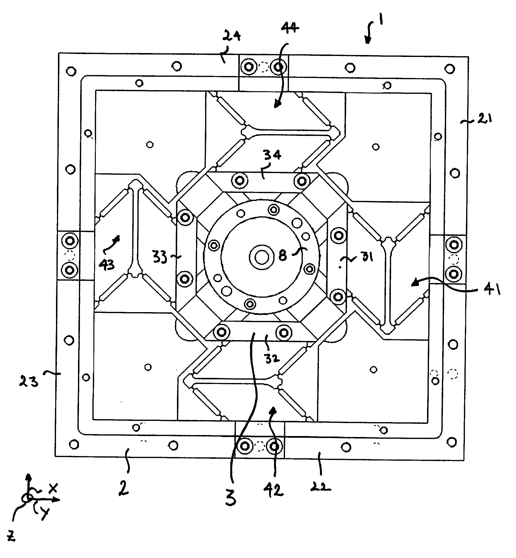
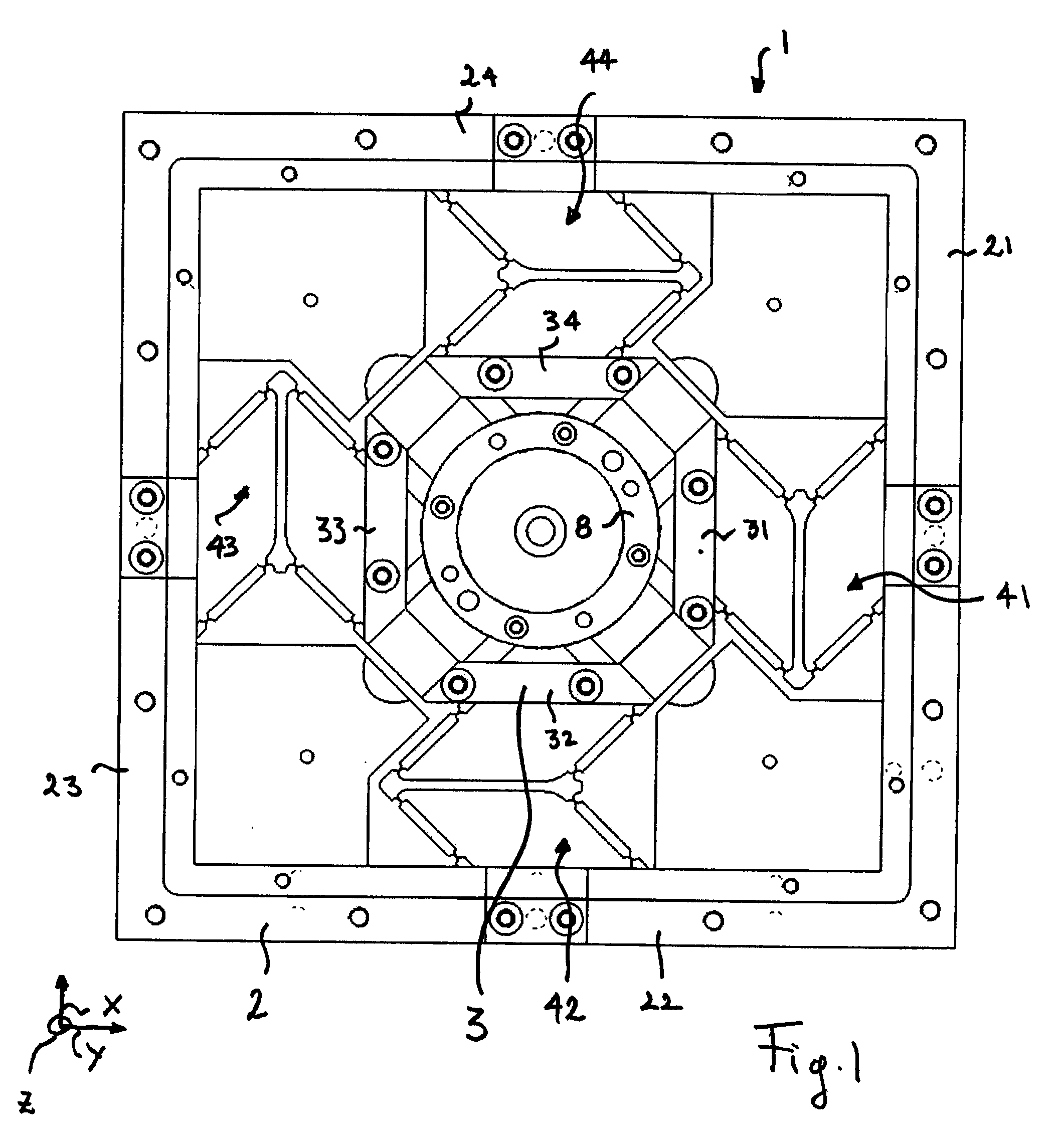
[0077]FIG. 1 depicts a biaxial precision positioning apparatus 1. The apparatus 1 comprises a stationary, rectangular hollow base or frame 2 and a rectangular stage 3, which is moveable in translation in a reference plane XY relative to the base 2. The reference plane XY is the geometric plane, which comprises the axes X and Y and is perpendicular to the axis Z. In use, the axis Z will preferably be vertical.

[0078]The base 2 comprises four ba...


PUM


Abstract

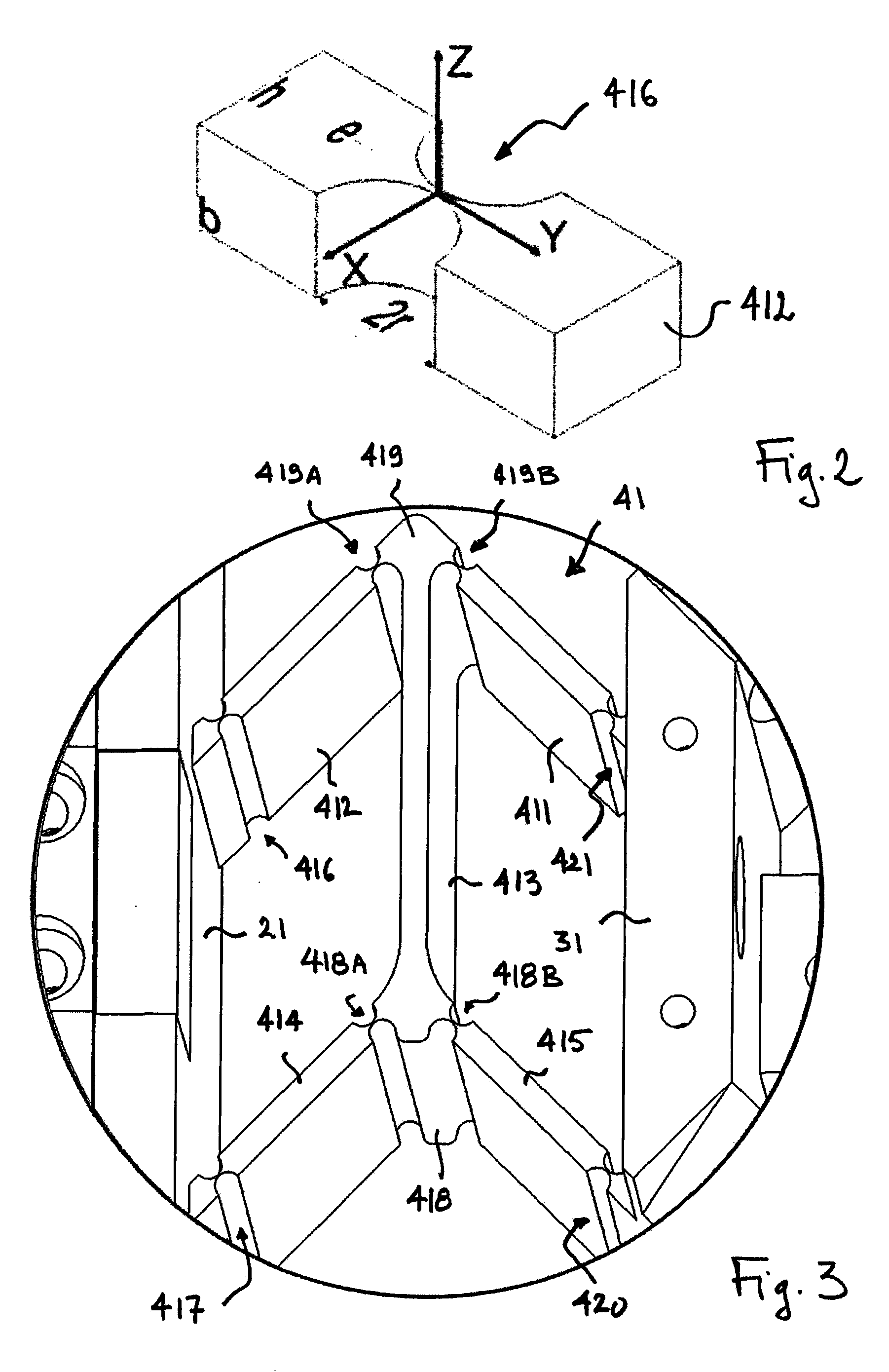
The invention relates to a precision positioning device comprising a base, moveable stage and four double parallelograms connecting the stage to the base. Each double parallelogram comprises six deformable vertices forming six pivots so that the stage can move in translation in a reference plane. Thanks to the four double parallelograms, the moveable stage is over-constrained so that the undesired rotational motions are very limited. The precision positioning device can further comprise a moveable platform connected to the moveable stage thanks to flexure strips. The moveable platform is over-constrained to only move in translation according to the Z axis.

Description

TECHNICAL FIELD[0001]The present invention relates to an ultra-precision positioning apparatus and more specifically to an ultra-precision positioning apparatus for precisely performing a fine positioning of the submicron order without rotational motion.BACKGROUND ART[0002]The importance of ultra-precision positioning technology has gradually increased in a variety of industrial fields. In particular, the development of ultra-precision measurements fields, such as atomic force microscope (AFM) or scanning electron microscope (SEM), has led to improved precision positioning technology.[0003]Various of ultra-positioning feeding devices are known. For example, the document U.S. Pat. No. 7,239,107 discloses a flexure positioning technique comprising a base, a moveable stage and a positioning mechanism coupled between the base and the stage to move the stage in translation. However, the positioning mechanism is very complex, which leads to increased risks of imprecision.[0004]Furthermore...

Claims


Application Information

Patent Timeline
Patent Type & Authority Applications(United States)
IPC IPC(8): G05G11/00
CPCB82Y35/00Y10T74/20207G01Q10/04
Inventor POYET, BENOITDAVID, JEANDUCOURTIEUX, SEBASTIEN
Owner POYET BENOIT
Learn More