System to eliminate electric actuator contamination

a technology of electric actuators and systems, applied in the field of actuators, can solve the problems of premature actuator wear and/or failure, ineffective removal of water vapor, and still susceptible to contamination of actuators, so as to reduce or eliminate actuator contamination, avoid reliability problems, and prolong the service life of actuators

Inactive Publication Date: 2010-11-04
THE BF GOODRICH CO
View PDF15 Cites 6 Cited by
  • Summary
  • Abstract
  • Description
  • Claims
  • Application Information

AI Technical Summary

Benefits of technology

[0009]The present invention provides a system to reduce or eliminate actuator contamination by providing a clean air source for the actuator. Thus, the void volume of the actuator can vary without introducing moisture and / or contaminants into the actuator thereby potentially extending the actuator service life and avoiding reliability issues that can result in aircraft downtime.

Problems solved by technology

While such modular actuators represent an improvement insofar as ease of replacement, the actuators are still susceptible to contamination due to the infiltration of moisture and / or contaminants.
Breathing can introduce moisture and / or contaminants into the actuator that can lead to premature actuator wear and / or failure (e.g., seizure).
Filters may provide a suitable solution in some instances, but generally are not effective at removing water vapor.

Method used


Image

  • System to eliminate electric actuator contamination
  • System to eliminate electric actuator contamination
  • System to eliminate electric actuator contamination

Examples


Embodiment Construction

[0023]Because the invention was conceived and developed for use in an aircraft braking system, it will be herein described chiefly in this context. However, the principles of the invention in their broader aspects can be adapted to other types of braking systems, such as in train brake systems.

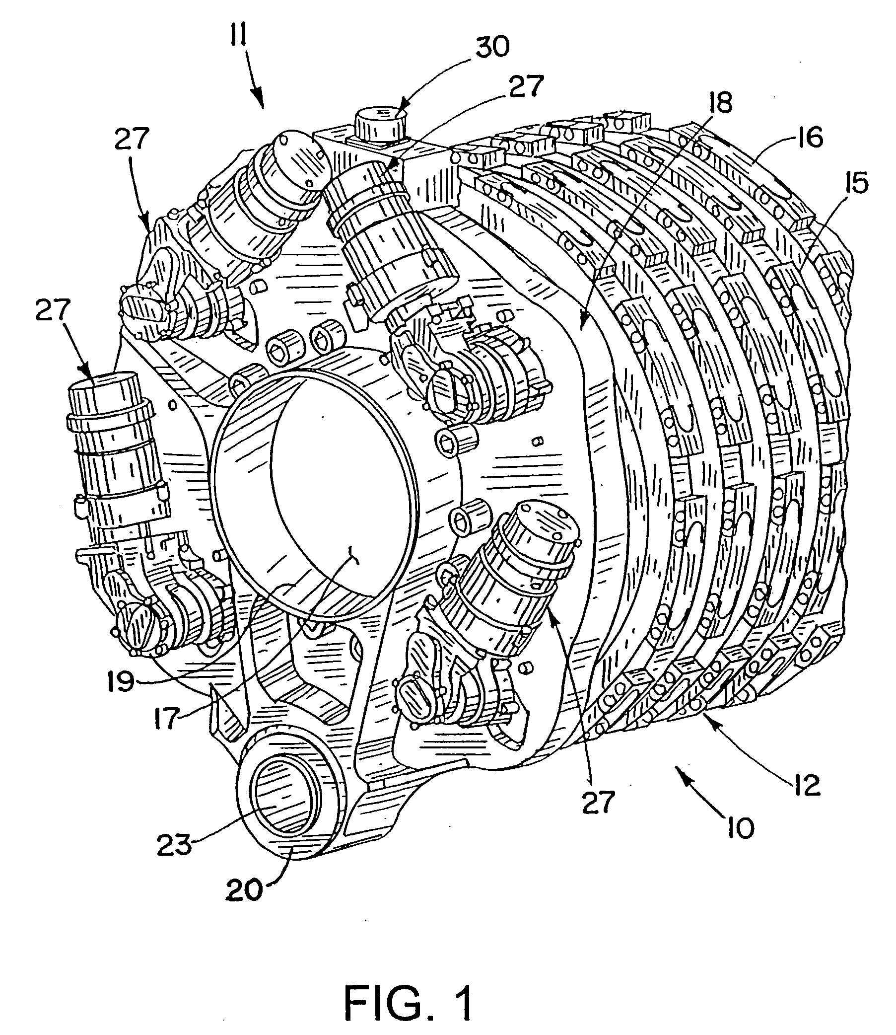
[0024]Referring now in detail to the drawings and initially to FIG. 1, an exemplary electric brake is generally indicated at 10. The brake 10 generally comprises a brake actuator assembly 11 and a heat sink in the form of a brake disk stack 12. The brake disk stack 12 can be of a conventional or other design including stationary brake elements and rotary brake elements that are interleaved and surround a torque tube or equivalent (not shown). The stationary and rotary brake elements usually are in the form of stator disks 15 and rotor disks 16. The stator disks 15 typically are splined to a torque tube 17 and the rotor disks 16 are splined to a wheel (not shown) interiorly of the wheel's rim. ...


PUM


Abstract

A system to reduce or eliminate brake actuator contamination by providing a clean air source for the actuator such that a volume of a void in the actuator can vary without introducing moisture and/or contaminants into the actuator. A movable wall moves in response to changes in the volume of the void of the actuator to compensate for the changes without drawing moisture or contaminants into the actuator housing. By reducing or eliminating actuator contamination the service life of the actuator can be extended.

Description

FIELD OF THE INVENTION[0001]The present invention relates generally to actuators and, more specifically, to actuators for brake systems.BACKGROUND OF THE INVENTION[0002]Known in the prior art are aircraft wheel and brake assemblies including a non-rotatable wheel support, a wheel mounted to the wheel support for rotation, and a brake disk stack having front and rear axial ends and alternating rotor and stator disks mounted with respect to the wheel support and wheel for relative axial movement. Each rotor disk is coupled to the wheel for rotation therewith and each stator disk is coupled to the wheel support against rotation. A back plate is located at the rear end of the disk stack and a brake head is located at the front end. The brake head houses a plurality of actuator rams that extend to compress the brake disk stack against the back plate. Torque is taken out by the stator disks through a static torque tube or the like.[0003]Electrically actuated aircraft brakes of various con...

Claims


Application Information

Patent Timeline
Patent Type & Authority Applications(United States)
IPC IPC(8): F16D55/00F16D55/22
CPCB60T13/741B60T17/221F16D65/18F16D2127/00F16D2125/40F16D2125/48F16D2121/24B60T13/36
Inventor CAHILL, ERIC D.
Owner THE BF GOODRICH CO
Why Eureka
Try Eureka