
Collapsible clothes hanger structure

a clothes hanger and collapsible technology, applied in the field of automatic clothes hangers, can solve problems such as not working as expected, and achieve the effects of convenient and quick fixing, not blown away, and convenient installation

Inactive Publication Date: 2010-11-04
YANG YEN TANG
View PDF24 Cites 12 Cited by
  • Summary
  • Abstract
  • Description
  • Claims
  • Application Information

AI Technical Summary

Benefits of technology

[0026]It is the primary object of the present invention to provide a collapsible clothes hanger structure, which may be adjusted to control the clothes hanger automatically or manually.
[0031]It is a still further object of the present invention to provide a collapsible clothes hanger structure, which can be controlled remotely.
[0033]It is a still further object of the present invention to provide a collapsible clothes hanger structure, which provides a hanging unit that does not require any fastener, which is easy to install and to work precisely.
[0034]It is a still further object of the present invention to provide a collapsible clothes hanger structure, which provides a tent to protect the clothes from getting wet by rain or humid.
[0036]It is a still further object of the present invention to provide a collapsible clothes hanger structure, wherein the clothes are securely connected to the hangers by the cooperation of the hangers and the clips, and the clothes are not blown away by strong wind.
[0037]It is a still further object of the present invention to provide a collapsible clothes hanger structure, wherein the positioning ropes are conveniently and quickly fixed to the first and second transverse rods and are not blown away by strong wind.

Problems solved by technology

The above-mentioned clothes hangers comprise a sensor to detect the weather, however, they are not provided with proper definitions about the weather so that they can not work as expected.

Method used


Image

  • Collapsible clothes hanger structure
  • Collapsible clothes hanger structure
  • Collapsible clothes hanger structure

Examples


Embodiment Construction

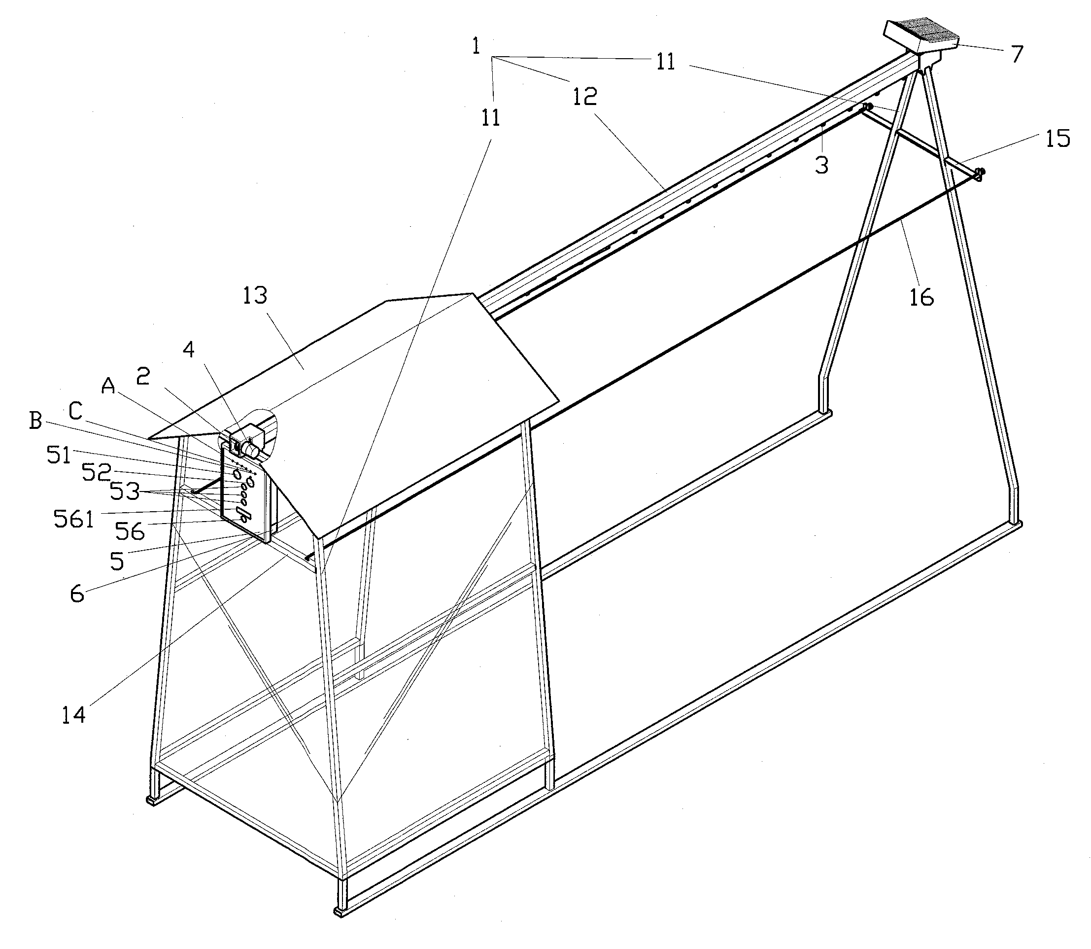
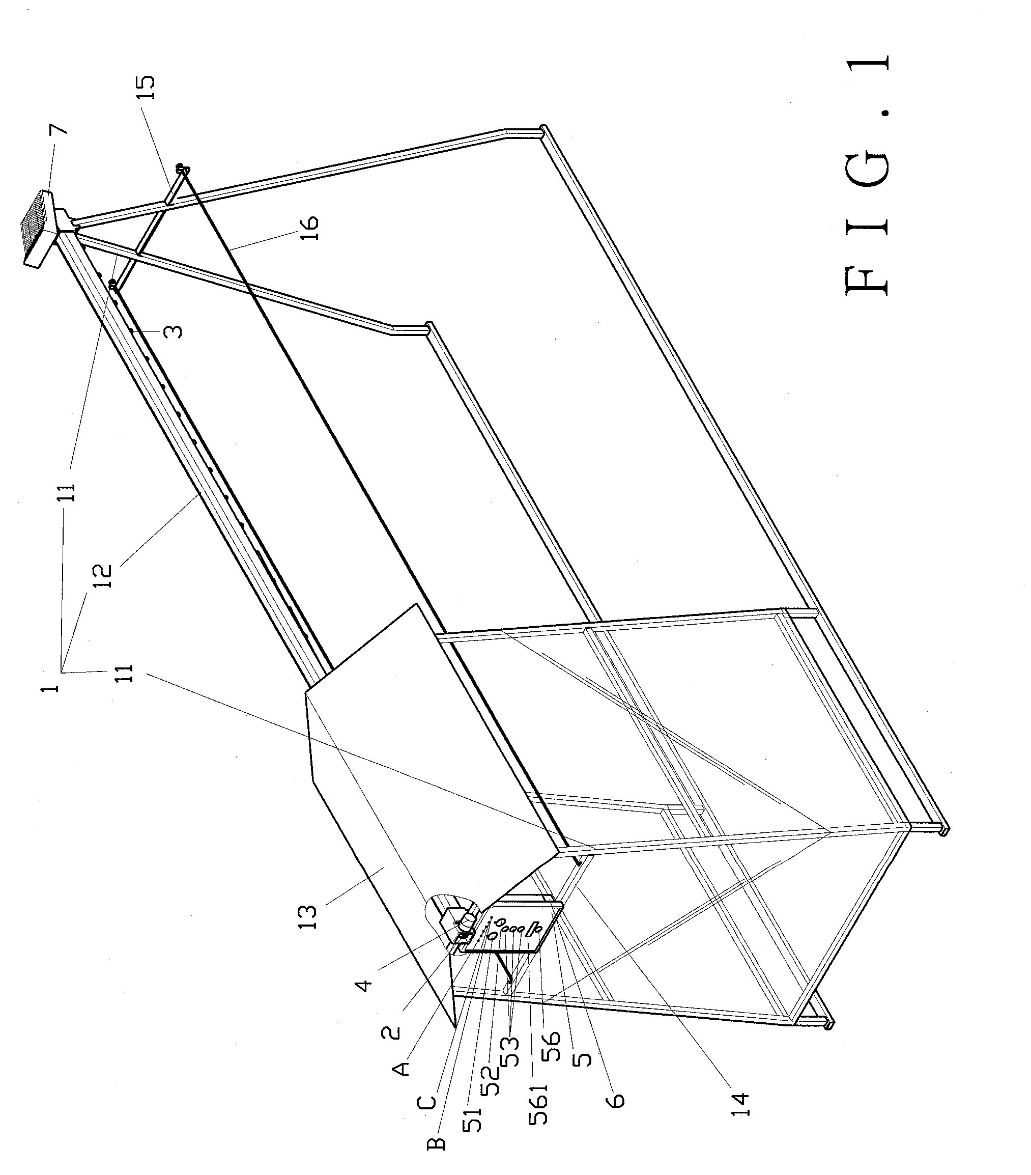
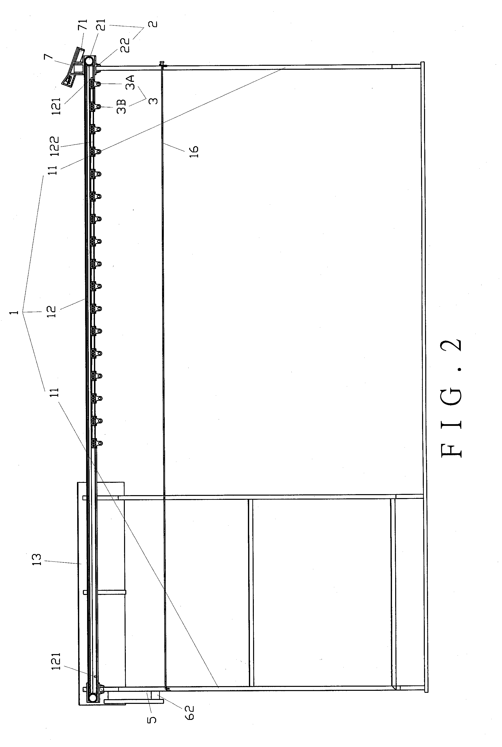
[0055]As shown in FIGS. 1 through 5, a preferred embodiment of the present invention comprises a frame 1, a transmission unit 2, a hanging unit 3, a motor 4, a control unit 5, a battery 6 and a solar energy board 7.

[0056]The frame 1 comprises a pair of supporting legs 11 and a rail 12. The rail 12 is secured between the supporting legs 11. A tent 13 is provided on the frame 1 and covers a portion of the rail 12 to protect clothes from being wet by rain or dew. In addition, the two supporting legs 11 respectively have a first transverse rod 14 and a second transverse rod 15. The first transverse rod 14 is located close to the tent 13 and the second transverse rod 15 is located remote from the tent 13. Referring to FIGS. 12 to 16, there are three fixing holes 141 in each of two ends of the first transverse rod 14, and two engaging members 151 are respectively connected to two ends of the second transverse rod 15. Two positioning ropes 16 are connected between the first and second tran...


PUM


Abstract

A collapsible clothes hanger structure includes a frame including a pair of supporting legs and a rail. A rail is secured between the supporting legs. A tent is provided on the frame and the tent covers a portion of the rail. A transmission unit includes a transmission gear meshing with a transmission belt. The transmission gear and the transmission belt are disposed in the rail. Multiple hanging units are movably disposed in the rail in sequence. A motor is connected to and drives the transmission unit in the rail to control the hanging units to slide along the rail. A control unit is coupled with a light sensor, a water drop sensor, and a timer. The control unit collects signals from any of the light sensor, the water drop sensor, and the timer to control the motor and the hanging unit. By the structure, the collapsible clothes hanger is automatically expanded or retracted according to light and rain or the pre-set time.

Description

[0001]This is a Continuation-In-Part application of U.S. patent application Ser. No. 11 / 951,566, filed on Dec. 6, 2007, currently pending.BACKGROUND OF THE INVENTION[0002]1. Field of the Invention[0003]A conventional automatic clothes hanger comprises a main body having a platform extending outwardly for a motor and a control circuit to be secured and connected thereon. The platform is provided with a support frame and accessories. The support frame is provided with a micro switch and a sensor at the two respective ends to detect the weather and to control the clothes hanger to extend or to collapse.[0004]2. Description of the Prior Art[0005]Another conventional automatic clothes hanger comprises a basic frame, a swivel frame, an adjusting frame and a fixture, and is incorporated with a sensor to extend or to collapse the clothes hanger. The swivel frame is linked to activate simultaneously to assist the clothes hanger to extend or to collapse.[0006]The above-mentioned clothes hange...

Claims


Application Information

Patent Timeline
IPC IPC(8): D06F57/00
CPCA47G25/486D06F57/06D06F53/04D06F53/005
Inventor YANG, YEN-TANG
Owner YANG YEN TANG
Learn More